Machinery Spaces
Home || Diesel Engines ||Boilers||Feed Systems ||Steam Turbines ||Fuel Treatment ||Pumps ||Refrigeration ||

Shunt Wound d.c. Motor, Series Wound d.c. Motor & d.c. Motor Starter

When a current is supplied to a single coil of wire in a magnetic field a force is created which rotates the coil. This is a similar situation to the generation of current by a coil moving in a magnetic field. In fact generators and motors are almost interchangeable, depending upon which two of magnetic field, current and motion are provided.

ships machinery spaces
container ships machinery info
Additional coils of wire and more magnetic fields produce a more efficient motor. Interpoles are fitted to reduce sparking but now have opposite polarity to the next main pole in the direction of rotation, When rotating the armature acts as a generator and produces current in the reverse direction to the supply. This is known as back e.m.f. (electromotive force) and causes a voltage drop across the motor. This back e.m.f. controls the power used by the motor but is not present as the motor is started. As a result, to avoid high starting currents special control circuits or starters are used.

The behaviour of the d.c. motor on load is influenced by the voltage drop across the armature, the magnetic field produced between the poles and the load or torque on the motor. Some of these factors are interdependent. For example, the voltage drop across the armature depends upon the back e.m.f. which depends upon the speed of the motor and the strength of the magnetic field. Shunt, series and compound windings are used to obtain different motor characteristics by varying the above factors.

Shunt wound d.c. motor

Fig: Shunt wound d.c. motor

The shunt wound motor has field windings connected in parallel with the armature windings. Thus when the motor is operating with a fixed load at constant speed all other factors are constant. An increase in load will cause a drop in speed and therefore a reduction in back e.m.f. A greater current will then flow in the armature windings and the motor power consumption will rise: the magnetic field will be unaffected since it is connected in parallel. Speed reduction is, in practice, very small, which makes the shunt motor an ideal choke for constant-speed variable-load duties.


Series wound d.c. motor

Fig: Series wound d.c. motor

The series motor has field windings connected in series with the armature windings . With this arrangement an increase in load will cause a reduction in speed and a fall in back e.m.f. The increased load current will, however, now increase the magnetic field and therefore the back e.m.f. The motor will finally stabilise at some reduced value of speed. The series motor speed therefore changes considerably with load.

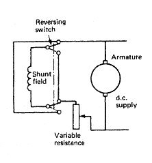
Control of d.c. motors is quite straightforward. The shunt wound motor has a variable resistance in the field circuit, as shown in Figure . This permits variation of the current in the field coils and also the back e.m.f., giving a range of constant speeds. To reverse the motor the field current supply is reversed, as shown in Figure .

One method of speed control for a series wound motor has a variable resistance in parallel with the field coils. Reverse operation is again achieved by reversing the field current supply as shown in Figure .


In operation the shunt wound motor runs at constant speed regardless of load. The series motor runs at a speed determined by the load, the greater the load the slower the speed. Compounding—the use of shunt and series field windings—provides a combination of these characteristics. Starting torque is also important. For a series wound motor the starting torque is high and it reduces as the load increases. This makes the series motor useful for winch and crane applications. It should be noted that a series motor if started on no-load has an infinite speed. Some small amount of compounding is usual to avoid this dangerous occurrence. The shunt wound motor is used where constant speed is required regardless of load; for instance, with fans or pumps. The starting of a d.c. motor requires a circuit arrangement to limit armature current. This is achieved by the use of a starter .

d.c. motor starter

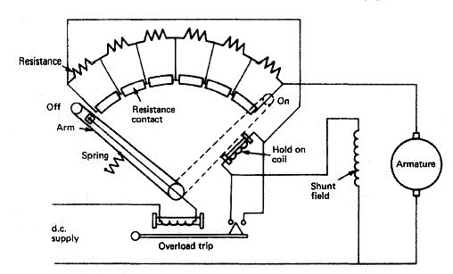
Fig: d.c. motor starter


A number of resistances are provided in the armature and progressively removed as the motor speeds up and back e.m.f. is developed. An arm, as part of the armature circuit, moves over resistance contacts such that a number of resistances are first put into the armature circuit and then progressively removed. The arm must be moved slowly to enable the motor speed and thus the back e.m.f. to build up. At the final contact no resistance is in the armature circuit. A 'hold on' or 'no volts' coil holds the starter arm in place while there is current in the armature circuit.

If a loss of supply occurs the arm will be released and returned to the 'off position by a spring. The motor must then be started again in the normal way. An overload trip is also provided which prevents excess current by shorting out the 'hold on* coil and releasing the starter arm. The overload coil has a soft iron core which, when magnetised sufficiently by an excess current, attracts the trip bar which shorts out the hold on coil. This type of starter is known as a 'face plate'; other types make use of contacts without the starting handle but introduce resistance into the armature circuit in much the same way.


Related Info:

  1. A.C. motors for ships machinery
  2. Supplying alternating current to a coil which is free to rotate in a magnetic field will not produce a motor effect since the current is constantly changing direction. Use is therefore made in an induction or squirrel cage motor of a rotating magnetic field produced by three separately phased windings in the stator. ...

  3. Use of A.C. generators
  4. A coil of wire rotating in a magnetic field produces a current. The current can be brought out to two slip rings which are insulated from the shaft. Carbon bushes rest on these rings as they rotate and collect the current for use in an external circuit. Current collected in this way will be alternating, that is, changing in direction and rising and falling in value. To increase the current produced, additional sets of poles may be introduced....

  5. D.C. motors for ships machinery
  6. When a current is supplied to a single coil of wire in a magnetic field a force is created which rotates the coil. This is a similar situation to the generation of current by a coil moving in a magnetic field. In fact generators and motors are almost interchangeable, depending upon which two of magnetic field, current and motion are provided.....

  7. Use of D.C. generators
  8. A current is produced when a single coil of wire is rotated in a magnetic field. When the current is collected using a ring which is split into two halves (a commutator), a direct or single direction current is produced. The current produced may be increased by the use of many turns of wire and additional magnetic fields....

  9. Emergency power supply for ships machinery operation
  10. In the event of a main generating system failure an emergency supply of electricity is required for essential services. This can be supplied by batteries, but most merchant ships have an emergency generator. The unit is diesel driven and located outside of the machinery space .

  11. Maintenance requirement for ships electrical equipment
  12. With all types of electrical equipment cleanliness is essential for good operation. Electrical connections must be sound and any signs of sparking should be investigated. Parts subject to wear must be examined and replaced when necessary. ...

  13. Choice of batteries for ships machinery spaces - Lead acid and alkaline batteries
  14. The battery is a convenient means of storing electricity. It is used on many ships as an instantly available emergency supply. It may also be used on a regular basis to provide a low-voltage d.c. supply to certain equipment.....

  15. Ships battery maintenance guidance
  16. The electrolyte level should be maintained just above the top of the plates. Any liquid loss due to evaporation or chemical action should be replaced with distilled water. Only in an emergency should other water be used. It is not usual to add electrolyte to batteries.....

  17. Operating characteristics of battery for ships machinery spaces
  18. Having been 'discharged' by delivering electrical power a battery must then be 'charged' by receiving electrical power. To charge the battery an amount of electrical power must be provided in the order of the capacity.....

  19. Insulation resistance measurement
  20. Good insulation resistance is essential to the correct operation of electrical equipment. A means must be available therefore to measure insulation resistance. Readings taken regularly will give an indication as to when and where corrective action, maintenance, servicing, etc., is required....

  21. Use of navigational light circuits
  22. The supply to the navigation lights circuit must be maintained under all circumstances and special provisions are therefore made. To avoid any possibility of accidental open circuits the distribution board for the navigation lights supplies no other circuit.....

  23. Ward—Leonard speed control system
  24. As a very flexible, reliable means of motor speed control the Ward-Leonard system is unmatched.The system is made up of a driving motor which runs at almost constant speed and powers a d.c. generator .....

  25. Danger of electric shock to human body
  26. The resistance of the human body is quite high only when the skin is dry. The danger of electric shock is therefore much greater for persons working in a hot, humid atmosphere since this leads to wetness from body perspiration.....


Marine machineries - Useful tags

Marine diesel engines ||Steam generating plant ||Air conditioning system ||Compressed air ||Marine batteries ||Cargo refrigeration ||Centrifugal pump ||Various coolers ||Emergency power supply ||Exhaust gas heat exchangers ||Feed system ||Feed extraction pump || Flow measurement || Four stroke engines || Fuel injector || Fuel oil system || Fuel oil treatment ||Gearboxes || Governor || Marine incinerator || Lub oil filters || MAN B&W engine || Marine condensers || Oily water separator || Overspeed protection devices || Piston & piston rings || Crankshaft deflection || Marine pumps || Various refrigerants || Sewage treatment plant || Propellers || Power Plants || Starting air system || Steam turbines || Steering gear || Sulzer engine || Turbine gearing || Turbochargers || Two stroke engines || UMS operations || Drydocking & major repairs || Critical machinery || Deck machineries & cargo gears || Control and instrumentation ||Fire protection ||Engine room safety ||


Machinery Spaces.com is about working principles, construction and operation of all the machinery items in a ship intended primarily for engineers working on board and those who working ashore . For any remarks please Contact us

Copyright © 2010-2016 Machinery Spaces.com All rights reserved.
Terms and conditions of use
Read our privacy policy|| Home page||