Machinery Spaces
Home || Diesel Engines ||Boilers||Feed Systems ||Steam Turbines ||Fuel Treatment ||Pumps ||Refrigeration ||

Displacement, Axial flow and Centrifugal Pumps for Ship Use

A pump is a machine used to raise liquids from a low point to a high point. Alternatively it may simply provide the liquid with an increase in energy enabling it to flow or build up a pressure. The pumping action can be achieved in various ways according to the type of pump employed. The arrangement of pipework, the liquid to be pumped and its purpose will result in certain system requirements or characteristics that must be met by the pump.

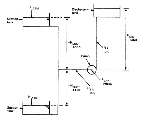
A pumping system on a ship will consist of suction piping, a pump and discharge piping . The system is arranged to provide a positive pressure or head at some point and discharge the liquid. The pump provides the energy to develop the head and overcome any losses in the system. Losses are mainly due to friction within the pipes and the difference between the initial and final liquid levels.

ships machinery spaces
container ships machinery info
To obtain the best operating conditions for the pump it should operate over its range of maximum efficiency.
Basic pumping system

Fig: Basic pumping system on board
HsucrrTANK= height of suction tank level above pump
(negative when tank level is below pump suction)

An important consideration, particularly when drawing liquids from below the pump, is the suction-side conditions of the system. The determination of Net Positive Suction Head (NPSH) is undertaken for both the system and the pump. Net Positive Suction Head is the difference between the absolute pump inlet pressure and the vapour pressure of the liquid, and is expressed in metres of liquid. Vapour pressure is temperature dependent and therefore NPSH should be given for the operating temperature of the liquid.

There are three main classes of pump in marine use: displacement, axial flow and centrifugal. A number of different arrangements are possible for displacement and centrifugal pumps to meet particular system characteristics.

Positive displacement pumps are pumps in which one or two chambers are filled and emptied. These include reciprocating, screw, gear and water ring type pumps. They do not require a priming device and may themselves be used as one. They cause a reduction and increase in volume of space and cause the liquid or gas to be physically moved.

Axial flow pump
Axial flow pump

Dynamic pressure pumps are pumps in which a tangential acceleration is imparted on the fluid. These include centrifugal flow, axial flow, and mixed flow types (the latter is a combination of centrifugal and axial flow), depending on the head they may require a priming device.


Sketch of centrifugal pump

The passage of water through a centrifugal pump : Water enters the pump axially through the eye, then by centrifugal action continues radially and discharges around the entire circumference. The fluid, in passing through the impeller, receives energy from the vanes giving an increase in pressure and velocity. The velocity, which is kinetic energy, is partly converted into pressure energy by suitable design of the impeller vanes and the pumps volute casing.

centrifugal-pump-impeller-and-volute-casing
Centrifugal pump impeller and volute casing

The centrifugal pump consists of a stainless steel shaft with keyway for the impeller, which is normally made of aluminium bronze and fitted by means of a bolt to the shaft. Replaceable wear rings/sealing rings are fitted to the pump casing and impeller, these separate the suction from the discharge side of the pump. The pump casing is normally made of gunmetal or cast iron but will depend on the pump's application. The sealing arrangement can be by means of gland packing or mechanical seal.

Read more on Centrifugal pump principles and working procedure


Reciprocating Pumps

The stroke of steam driven reciprocating pumps must be adjusted so that it is a maximum, as this then reduces "ridging" in the steam cylinders and pump barrels. Suction and delivery valves must be kept in good condition by regular attention.
Read more on Reciprocating displacement pumps

Rotary Pumps

Centrifugal and other types of rotary pumps usually depend on the maintenance of fine clearances for their successful operation. Attention must be given to see that the correct clearances are maintained, it must also be remembered that fine clearances are often destroyed through fitting joints of too thick material. The glands of rotary pumps are also important, in many cases the gland is arranged on the suction side of the pump and sealing connections are fitted. Again, if the pump efficiency is to be maintained, it is imperative that care and attention be given to this part.

After overhaul of rotary pumps, it is essential that the shaft alignment between the prime mover and the pumps is maintained, failure to maintain this alignment leads to gland trouble and excessive wear on shafts, and this is of particular importance to pumps fitted with gland seals.

Sketch of a gear pump

Sketch of a gear pump

In the gear pump sketched, fluid enters the suction side, drawn in by two gear wheels that are meshed together and are close fitting to the pump casing, and is carried round between the teeth of the gear and the casing. Such pumps are fairly efficient and smooth running and are best suited to pumping oils, ie good in fuel systems.Note: these pumps must also be fitted with a relief valve.

Sketch of a piston pump

Sketch of a piston pump

In the pump sketched below, fluid is entering the pump on the suction side when the piston is on the upward stroke, the bottom suction valve is open and the bottom discharge valve is closed, drawing in fluid at the bottom. At the same time, the discharge valve at the top is open and the top suction valve is closed, discharging water at the top and vice versa when the piston is on the downward stroke, meaning the piston is discharging and sucking on both strokes. The air vessel in the system is designed to take up any fluctuations in pressure.


Related Info:

  1. Various valves arrangement for machinery spaces piping system
  2. Straight-through cocks, Globe valve,Non-return valves,gate valves,Relief valves, quick closing valves, valve chests....

  3. Domestic water systems for general cargo ship
  4. Domestic water systems usually comprise a fresh water system for washing and drinking and a salt water system for sanitary purposes . Both use a basically similar arrangement of an automatic pump supplying the liquid to a tank which is pressurised by compressed air...

  5. Mud boxes, Suction pipes, Steam traps, Expansion pieces & Drains for Machinery space piping system
  6. The mud box is a coarse strainer with a straight tailpipe down to the bilge..Suction pipes in tanks should be arranged with a bell mouth or foot..An expansion piece is fitted in a pipeline which is subject to considerable temperature variations..Drains are provided in pipelines and usually have small cocks to open or close them.....

  7. Reciprocating displacement pumping system for ships use
  8. The displacement pumping action is achieved by the reduction or increase in volume of a space causing the liquid (or gas) to be physically moved. The method employed is either a piston in a cylinder using a reciprocating motion, or a rotating unit using vanes, gears or screws.

  9. Centrifugal pump principles and working procedure
  10. In a centrifugal pump liquid enters the centre or eye of the impeller and flows radially out between the vanes, its velocity being increased by the impeller rotation....

  11. How a pneumatically control valve works ?
  12. Many pneumatic devices use a nozzle and flapper system to give a variation in the compressed air signal.A typical pneumatic control valve is shown in Figure . It can be considered as made up of two parts—the actuator and the valve. A flexible diaphragm forms a pressure tight chamber in the upper half of the actuator and the controller signal is fed in.....

  13. Bilge and ballast systems for general cargo ships
  14. The bilge main is arranged to drain any watertight compartment other than ballast, oil or water tanks and to discharge the contents overboard. The number of pumps and their capacity depend upon the size, type and service of the vessel.....


Marine machineries - Useful tags

Marine diesel engines ||Steam generating plant ||Air conditioning system ||Compressed air ||Marine batteries ||Cargo refrigeration ||Centrifugal pump ||Various coolers ||Emergency power supply ||Exhaust gas heat exchangers ||Feed system ||Feed extraction pump || Flow measurement || Four stroke engines || Fuel injector || Fuel oil system || Fuel oil treatment ||Gearboxes || Governor || Marine incinerator || Lub oil filters || MAN B&W engine || Marine condensers || Oily water separator || Overspeed protection devices || Piston & piston rings || Crankshaft deflection || Marine pumps || Various refrigerants || Sewage treatment plant || Propellers || Power Plants || Starting air system || Steam turbines || Steering gear || Sulzer engine || Turbine gearing || Turbochargers || Two stroke engines || UMS operations || Drydocking & major repairs || Critical machinery || Deck machineries & cargo gears || Control and instrumentation ||Fire protection ||Engine room safety ||


Machinery Spaces.com is about working principles, construction and operation of all the machinery items in a ship intended primarily for engineers working on board and those who working ashore . For any remarks please Contact us

Copyright © 2010-2016 Machinery Spaces.com All rights reserved.
Terms and conditions of use
Read our privacy policy|| Home page||