Machinery Spaces
Home || Diesel Engines ||Boilers||Feed Systems ||Steam Turbines ||Fuel Treatment ||Pumps ||Refrigeration ||

Four-stroke Cycle Marine Diesel Engine

The four-stroke cycle is completed in four strokes of the piston, or two revolutions of the crankshaft. In order to operate this cycle the engine requires a mechanism to open and close the inlet and exhaust valves.

A cross-section of a four-stroke cycle engine is shown diagram. The engine is made up of a piston which moves up and down in a cylinder which is covered at the top by a cylinder head. The fuel injector, through which fuel enters the cylinder, is located in the cylinder head. The inlet and exhaust valves are also housed in the cylinder head and held shut by springs. The piston is joined to the connecting rod by a gudgeon pin.

ships machinery spaces
container ships machinery info
The bottom end or big end of the connecting rod is joined to the crankpin which forms part of the crankshaft. With this assembly the linear up-and-down movement of the piston is converted into rotary movement of the crankshaft.

4 stroke engine

The crankshaft is arranged to drive through gears the camshaft, which either directly or through pushrods operates rocker arms which open the inlet and exhaust valves. The camshaft is 'timed' to open the valves at the correct point in the cycle. The crankshaft is surrounded by the crankcase and the engine framework which supports the cylinders and houses the crankshaft bearings. The cylinder and cylinder head are arranged with water-cooling passages around them.


Comparison between two stroke cycle diesel engine and a four stroke engine
: The main difference between the two cycles is the power developed. The two-stroke cycle engine, with one working or power stroke every revolution, will, theoretically, develop twice the power of a four-stroke engine of the same swept volume. Inefficient scavenging however and other losses, reduce the power advantage .

For a particular engine power the two-stroke engine will be considerably lighter—an important consideration for ships. Nor does the two-stroke engine require the complicated valve operating mechanism of the four-stroke. The four-stroke engine however can operate efficiently at high speeds which offsets its power disadvantage; it also consumes less lubricating oil.

Each type of engine has its applications which on board ship have resulted in the slow speed (i.e. 80— 100 rev/min) main propulsion diesel operating on the two-stroke cycle. At this low speed the engine requires no reduction gearbox between it and the propeller.

The four-stroke engine (usually rotating at medium speed, between 250 and 750 rev/ min) is used for auxiliaries such as alternators and sometimes for main propulsion with a gearbox to provide a propeller speed of between 80 and 100 rev/min.

Connecting rod
Fig: Connecting rod

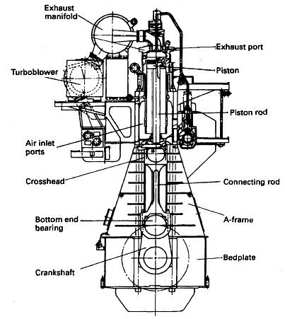
2 stroke engine

Fig: Two stroke engine

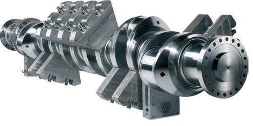
Crankshaft
Fig: Crankshaft

4 stroke engine

Fig: Four stroke engine


Main components

1. Engine block

The engine block is made of nodular cast iron in one piece for all cylinder numbers. The main bearing caps are fixed from below by two hydraulically tensioned screws. They are guided sideways by the engine block at the top as well as at the bottom. Hydraulically tensioned horizontal side screws support the main bearing caps.

2. Crankshaft: The crankshaft is forged in one piece. Counterweights are fitted on every web. High degree of balancing results in an even and thick oil film for all bearings.

3. Connecting rod : The connecting rod of alloy steel is forged and machined with round sections. The lower end is split horizontally to allow removal of piston and connecting rod through the cylinder liner. All connecting rod bolts are hydraulically tightened. The gudgeon pin bearing is of tri-metal type. Oil is led to the gudgeon pin bearing and to the piston through a bore in the connecting rod.

4. Main bearings and big end bearings : The big end bearings are of tri-metal type with steel back, lead bronze lining and a soft and thick running layer. Both tri-metal and bi-metal bearings are used as main bearings.

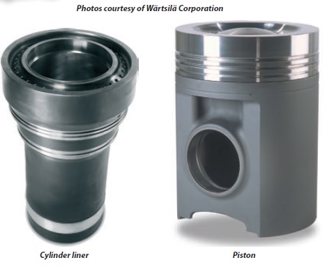
5. Cylinder liner : The centrifugally cast cylinder liner has a high and rigid collar to minimise deformations. The liner material is a special grey cast iron alloy developed for excellent wear resistance and high strength. Accurate temperature control is achieved with precisely positioned longitudinal cooling water bores. To eliminate the risk of bore polishing, the liner is equipped with an anti-polishing ring. The cooling water space between block and liner is sealed off by double O-rings. In the upper end the liner is equipped with an anti-polishing ring to eliminate bore polishing and reduce lube oil consumption.
cylinder liner & piston
Fig: Cylinder liner & piston


6. Piston and piston rings : The piston is of composite design with nodular cast iron skirt and steel crown. The piston skirt is pressure lubricated, which ensures a controlled oil distribution to the cylinder liner under all operating conditions. Oil is fed to cooling gallery in the piston top through the connecting rod. The piston ring grooves are hardened for good wear resistance. The piston ring set consists of two directional compression rings and one spring-loaded conformable oil scraper ring. All piston rings have a wear resistant chromium plating.

7. Cylinder head : The cylinder head is designed for easy maintenance with only four hydraulically tightened studs. No valve cages are used, which results in very good flow dynamics in the exhaust gas channel. The exhaust valve seats are water cooled and all valves are equipped with valve rotators. The seat faces of the inlet valves are Stellite-plated. In case the engine is specified for MDF operation only, also the exhaust valves are Stellite-plated. Engines that are intended for operation on HFO have Nimonic exhaust valves.


Marine diesel engine related other useful articles:
  1. Two stroke cycle diesel engines operational guideline

  2. The two-stroke cycle is completed in two strokes of the piston or one revolution of the crankshaft. In order to operate this cycle where each event is accomplished in a very short time, the engine requires a number of special arrangements.
    More .....

  3. Power measurement for marine diesel engine - The engine indicator

  4. There are two possible measurements of engine power: the indicated power and the shaft power. The indicated power is the power developed within the engine cylinder and can be measured by an engine indicator. The shaft power is the power available at the output shaft of the engine and can be measured using a torsionmeter or with a brake.
    More .....

  5. Supply of fresh air and removal of exhaust gases by a gas exchanger

  6. A basic part of the cycle of an internal combustion engine is the supply of fresh air and removal of exhaust gases. This is the gas exchange process. Scavenging is the removal of exhaust gases by blowing in fresh air.
    More .....

  7. The fuel oil system for a diesel engine

  8. The fuel oil system for a diesel engine can be considered in two parts—the fuel supply and the fuel injection systems. Fuel supply deals with the provision of fuel oil suitable for use by the injection system.
    More .....

  9. Lubricating oil system for a marine diesel engine - how it works

  10. The lubrication system of an engine provides a supply of lubricating oil to the various moving parts in the engine. Its main function is to enable the formation of a film of oil between the moving parts, which reduces friction and wear. The lubricating oil is also used as a cleaner and in some engines as a coolant.
    More .....

  11. Cooling of ships engine - how it works , requirement of fresh water & sea water cooling system

  12. Cooling of engines is achieved by circulating a cooling liquid around internal passages within the engine. The cooling liquid is thus heated up and is in turn cooled by a sea water circulated cooler. Without adequate cooling certain parts of the engine which are exposed to very high temperatures, as a result of burning fuel, would soon fail.
    More .....

  13. Starting air system for diesel engine - how it works

  14. Diesel engines are started by supplying compressed air into the cylinders in the appropriate sequence for the required direction. A supply of compressed air is stored in air reservoirs or 'bottles' ready for immediate use. Up to 12 starts are possible with the stored quantity of compressed air.
    More .....

  15. Governor-Function of governors controlling speed of marine diesel engine

  16. The principal control device on any engine is the governor. It governs or controls the engine speed at some fixed value while power output changes to meet demand. This is achieved by the governor automatically adjusting the engine fuel pump settings to meet the desired load at the set speed.
    More .....

  17. Cylinder relief valve of a marine diesel engine - operational guideline

  18. The cylinder relief valve is designed to relieve pressures in excess of 10% to 20% above normal. The operation of this device indicates a fault in the engine which should be discovered and corrected.
    More .....

  19. Explosion relief valve of a marine diesel engine

  20. As a practical safeguard against explosions which occur in a crankcase, explosion relief valves or doors are fitted. These valves serve to relieve excessive crankcase pressures and stop flames being emitted from the crankcase. They must also be self closing to stop the return of atmospheric air to the crankcase.
    More .....

  21. Turning gear operational guideline
    The turning gear or turning engine is a reversible electric motor which drives a worm gear which can be connected with the toothed flywheel to turn a large diesel. A slow-speed drive is thus provided to enable positioning of the engine parts for overhaul purposes.
    More .....

  22. Couplings, clutches and gearboxes of a marine diesel engine

  23. The principal control device on any engine is the governor. It governs or controls the engine speed at some fixed value while power output changes to meet demand. This is achieved by the governor automatically adjusting the engine fuel pump settings to meet the desired load at the set speed.
    More .....

  24. MAN B&W diesel engine - Basic principles and operational guideline

  25. It is one of the MC series introduced in 1982, and has a longer stroke and increased maximum pressure when compared with the earlier L-GF and L-GB designs.
    More .....

  26. Crankcase oil mist detector of a marine diesel engine

  27. It is one of the MC series introduced in 1982, and has a longer stroke and increased maximum pressure when compared with the earlier L-GF and L-GB designs.
    More .....

  28. Various Heat exchanger for running machinery on board cargo ships

  29. Shell and tube heat exchangers for engine cooling water and lubricating oil cooling have traditionally been circulated with sea water. The sea water is in contact with the inside of the tubes, tube plates and water boxes.
    More .....

  30. Guideline for Turbochargers safety and operational requirement

  31. Shell and tube heat exchangers for engine cooling water and lubricating oil cooling have traditionally been circulated with sea water. The sea water is in contact with the inside of the tubes, tube plates and water boxes.
    More .....

  32. Function of Piston & piston rings

  33. Piston forms the lower part of the combustion chamber. It seals the cylinder and transmits the gas pressure to the connecting rod. The Piston comprises of two pieces; the crown and the skirt.The crown of a piston is subject to mechanical and thermal stresses.
    More .....


Marine machineries - Useful tags

Marine diesel engines ||Steam generating plant ||Air conditioning system ||Compressed air ||Marine batteries ||Cargo refrigeration ||Centrifugal pump ||Various coolers ||Emergency power supply ||Exhaust gas heat exchangers ||Feed system ||Feed extraction pump || Flow measurement || Four stroke engines || Fuel injector || Fuel oil system || Fuel oil treatment ||Gearboxes || Governor || Marine incinerator || Lub oil filters || MAN B&W engine || Marine condensers || Oily water separator || Overspeed protection devices || Piston & piston rings || Crankshaft deflection || Marine pumps || Various refrigerants || Sewage treatment plant || Propellers || Power Plants || Starting air system || Steam turbines || Steering gear || Sulzer engine || Turbine gearing || Turbochargers || Two stroke engines || UMS operations || Drydocking & major repairs || Critical machinery || Deck machineries & cargo gears || Control and instrumentation ||Fire protection ||Engine room safety ||


Machinery Spaces.com is about working principles, construction and operation of all the machinery items in a ship intended primarily for engineers working on board and those who working ashore . For any remarks please Contact us

Copyright © 2010-2016 Machinery Spaces.com All rights reserved.
Terms and conditions of use
Read our privacy policy|| Home page||