Machinery Spaces.com
Home || Diesel engines
||Boilers||Feed systems
||Steam turbines ||Fuel treatment ||Pumps ||Valves ||Refrigeration ||
Ships electrical plant and distribution system for the A.C. generators
Alternating current (AC) –
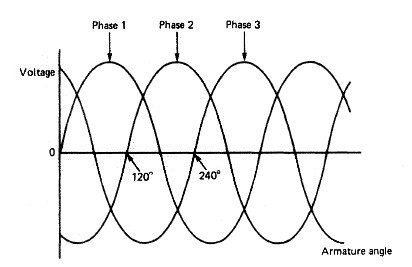
Alternating current is a form of electricity in which the current
alternates in direction (and the voltage alternates in polarity) at a frequency defined by
the generator (usually between 50 and 60 times per second, i.e., 50 – 60 hertz). AC was
adopted for power transmission in the early days of electricity supply because it had
two major advantages over direct current (DC): its voltage could be stepped up or down
according to need using transformers, and it could be interrupted more easily than DC.
Neither advantage is as relevant today as it once was because power electronics can
solve both issues for DC.
How alternating current is produced onboard ?
A coil of wire rotating in a magnetic field produces a current. The
current can be brought out to two slip rings which are insulated from the
shaft. Carbon bushes rest on these rings as they rotate and collect the
current for use in an external circuit. Current collected in this way will
be alternating, that is, changing in direction and rising and falling in
value. To increase the current produced, additional sets of poles may be
introduced.
The magnetic field is provided by electromagnets so arranged that
adjacent poles have opposite polarity. These 'field coils', as they are
called, are connected in series to an external source or the machine
output.
If separate coils or conductors are used then several outputs can be
obtained. Three outputs are usually arranged with a phase separation of
120°, to produce a three-phase supply.
The supply phasing is shown in fig below
. The three-phase system is more efficient in that for the
same mechanical power a greater total electrical output is obtained. Each
of the three outputs may be used in single-phase supplies or in
conjunction for a three-phase supply. The separate supplies are
connected in either star or delta formation .

Fig: Three-phase alternator output
The star
formation is most commonly used and requires four sliprings on the
alternator. The three conductors are joined at a common slipring and
also have their individual siipring. The central or neutral line is common
to each phase. The delta arrangement has two phases joined at each of
the three sliprings on the alternator. A single-phase supply can be taken
from any two sliprings.

Fig: Star and delta three-phase connections
So far, alternator construction has considered the armature rotating
and the field coils stationary. The same electricity generating effect is
produced if the reverse occurs, that is, the field coils rotate and the
armature is stationary. This is in fact the arrangement adopted for large,
heavy duty alternators.
The field current supply in older machines comes from a low-voltage
direct current generator or exciter on the same shaft as the alternator.
Modern machines, however, are either statically excited or of the
high-speed brushless type. The exciter is required to operate to counter
the effects of power factor for a given load.
The power factor is a
measure of the phase difference between voltage and current and is
expressed as the cosine of the phase angle. With a purely resistance load
the voltage and current are in phase, giving a power factor of one. The
power consumed is therefore the product of voltage and current.
Inductive or capacitive loads, combined with resistance loads, produce
lagging or leading power factors which have a value less than one. The
power consumed is the product of current, voltage and power factor.
The alternating current generator supplying a load has a voltage drop
resulting from the load. When the load has a lagging power factor this
voltage drop is considerable. Therefore the exciter, in maintaining the
alternator voltage, must vary with the load current and also the power
factor. The speed change of the prime mover must also be taken into
account.
Hand control of excitation is difficult so use is made of an automatic
voltage regulator (AVR). The AVR consists basically of a circuit fed
from the alternator output voltage which detects small changes in
voltage and feeds a signal to an amplifier which changes the excitation to
correct the voltage. Stabilising features are also incorporated in the
circuits to avoid 'hunting' (constant voltage fluctuations) or overcorrecting.
Various designs of AVR are in use which can be broadly divided
into classes such as carbon pile types, magnetic amplifiers, electronic
types, etc,
The statically excited alternator has a static excitation system instead
of a d.c. exciter. This type of alternator will more readily accept the
sudden loading by direct on-line starting of large squirrel cage motors.
The static excitation system uses transformers and rectifiers to provide
series and shunt components for the alternator field, that is, it is
compounded. Brushes and sliprings are used to transfer the current to
the field coils which are mounted on the rotor.
The terminal voltage
from the alternator thus gives the no-load voltage arid the load current
provides the extra excitation to give a steady voltage under any load
condition. The careful matching of components provides a system which
functions as a self regulator of voltage. Certain practical electrical
problems and the compensation necessary for speed variation require
that a voltage regulator is also built into the system.
The brushless high speed alternator was also developed to eliminate
d.c. exciters with their associated commutators and brushgear. The
alternator and exciter rotors are on a common shaft, which also carries
the rectifiers. The exciter output is fed to the rectifiers and then through
conductors in the hollow shaft to the alternator field coils. An automatic
voltage regulator is used with this type of alternator.

Fig: Alternator construction
The construction of an alternator can be seen in Figure above. The
rotor houses the poles which provide the field current, and these are
usually of the salient or projecting-pole type. Slip rings and a fan are also
mounted on the rotor shaft, which is driven by the auxiliary engine. The
stator core surrounds the rotor and supports the three separate phase
windings. Heat is produced in the various windings and must be
removed by cooling. The shaft fan drives air over a water-cooled heat
exchanger. Electric heaters are used to prevent condensation on the
windings when the alternator is not in use.
In addition to auxiliary-engine-driven alternators a ship may have a
shaft-driven alternator. In this arrangement a drive is taken from the
main engine or the propeller shaft and used to rotate the alternator. The
various operating conditions of the engine will inevitably result in
variations of the alternator driving speed. A hydraulic pump and
gearbox arrangement may be used to provide a constant-speed drive, or
the alternator output may be fed to a static frequency converter. In the
static frequency converter the a.c. output is first rectified into a variable
d.c. voltage and then inverted back into a three-phase a.c. voltage. A
feedback system in the oscillator inverter produces a constant-output a.c,
voltage and frequency.

Fig: A.C. distribution system
Distribution system
An a.c. distribution system is provided from the main switchboard which
is itself supplied by the alternators (Figure above). The voltage at the
switchboard is usually 440 volts, but on some large installations it may be
as high as 3300 volts. Power is supplied through circuit breakers to
larger auxiliaries at the high voltage. Smaller equipment may be
supplied via fuses or miniature circuit breakers. Lower voltage supplies
used, for instance, for lighting at 220 volts, are supplied by step down
transformers in the distribution network.
The distribution system will be three-wire with insulated or earthed
neutral. The insulated neutral has largely been favoured, but earthed
neutral systems have occasionally been installed. The insulated neutral
system can suffer from surges of high voltage as a result of switching or
system faults which could damage machinery. Use of the earthed system
could result in the loss of an essential service such as the steering gear as
a result of an earth fault. An earth fault on the insulated system would
not, however, break the supply and would be detected in the earth lamp
display. Insulated systems have therefore been given preference since
earth faults are a common occurrence on ships and a loss of supply in
such situations cannot be accepted.
In the distribution system there will be circuit breakers and fuses, as
mentioned previously for d.c. distribution systems. Equipment for a.c.
systems is smaller and lighter because of the higher voltage and
therefore lower currents. Miniature circuit breakers are used for
currents up to about 100 A and act as a fuse and a circuit breaker. The
device will open on overload and also in the event of a short circuit.
Unlike a fuse, the circuit can be quickly remade by simply closing the
switch. A large version of this device is known as the 'moulded-case
circuit breaker' and can handle currents in excess of 1000 A. Preferential
tripping and earth fault indication will also be a part of the a.c.
distribution system. These two items have been mentioned previously
for d.c. distribution systems.
Alternating current supply
Three-phase alternators arranged for parallel operation require a
considerable amount of instrumentation. This will include ammeters,
wattmeter, voltmeter, frequency meter and a synchronising device. Most
of these instruments will use transformers to reduce the actual values
taken to the instrument. This also enables switching, for instance,
between phases or an incoming machine and the bus-bars, so that one
instrument can display one of a number of values. The wattmeter
measures the power being used in a circuit, which, because of the power
factor aspect of alternating current load, will be less than the product of
the volts and amps. Reverse power protection is provided to alternators
since reverse current protection cannot be used. Alternatively various
trips may be provided in the event of prime mover failure to ensure that
the alternator does not act as a motor.
The operation of paralleling two alternators requires the voltages to
be equal and also in phase. The alternating current output of any
machine is always changing, so for two machines to operate together
their voltages must be changing at the same rate or frequency and be
reaching their maximum (or any other value) together. They are then
said to be 'in phase'. Use is nowadays made of a synchroscope when
paralleling two a.c. machines. The synchroscope has two windings which
are connected one to each side of the paralleling switch. A pointer is free
to rotate and is moved by the magnetic effect of the two windings. When
the two voltage supplies are in phase the pointer is stationary in the 12
o'clock position. If the pointer is rotating then a frequency difference
exists and the dial is marked for clockwise rotation FAST and
anti-clockwise rotation SLOW, the reference being to the incoming
machine frequency.
To parallel an incoming machine to a running machine therefore it is
necessary to ensure firstly that both voltages are equal Voltmeters are
provided for this purpose. Secondly the frequencies must be brought
into phase. In practice the synchroscope usually moves slowly in the FAST
direction and the paralleling switch is closed as the pointer reaches the
11 o'clock position. This results in the incoming machine immediately
accepting a small amount of load.
A set of three lamps may also be provided to enable synchronising.
The sequence method of lamp connection has a key lamp connected
across one phase with the two other lamps cross connected over the
other two phases. If the frequencies of the machines are different the
lamps will brighten and darken in rotation, depending upon the
incoming frequency being FAST or SLOW. The correct moment for
synchronising is when the key lamp is dark and the other two are equally
bright.
Related Info:
- A.C. motors for ships machinery
Supplying alternating current to a coil which is free to rotate in a magnetic field will not produce a motor effect since the current is constantly changing direction. Use is therefore made in an induction or squirrel cage motor of a rotating magnetic field produced by three separately phased windings in the stator. ...
-
Use of A.C. generators
A coil of wire rotating in a magnetic field produces a current. The current can be brought out to two slip rings which are insulated from the shaft. Carbon bushes rest on these rings as they rotate and collect the current for use in an external circuit. Current collected in this way will be alternating, that is, changing in direction and rising and falling in value. To increase the current produced, additional sets of poles may be introduced....
-
D.C. motors for ships machinery
When a current is supplied to a single coil of wire in a magnetic field a force is created which rotates the coil. This is a similar situation to the generation of current by a coil moving in a magnetic field. In fact generators and motors are almost interchangeable, depending upon which two of magnetic field, current and motion are provided.....
-
Use of D.C. generators
A current is produced when a single coil of wire is rotated in a magnetic field. When the current is collected using a ring which is split into two halves (a commutator), a direct or single direction current is produced. The current produced may be increased by the use of many turns of wire and additional magnetic fields....
-
Emergency power supply for ships machinery operation
In the event of a main generating system failure an emergency supply of electricity is required for essential services. This can be supplied by batteries, but most merchant ships have an emergency generator. The unit is diesel driven and located outside of the machinery space .
-
Maintenance requirement for ships electrical equipment
With all types of electrical equipment cleanliness is essential for good operation. Electrical connections must be sound and any signs of sparking should be investigated. Parts subject to wear must be examined and replaced when necessary. ...
-
Choice of batteries for ships machinery spaces - Lead acid and alkaline batteries
The battery is a convenient means of storing electricity. It is used on many ships as an instantly available emergency supply. It may also be used on a regular basis to provide a low-voltage d.c. supply to certain equipment.....
-
Ships battery maintenance guidance
The electrolyte level should be maintained just above the top of the plates. Any liquid loss due to evaporation or chemical action should be replaced with distilled water. Only in an emergency should other water be used. It is not usual to add electrolyte to batteries.....
-
Operating characteristics of battery for ships machinery spaces
Having been 'discharged' by delivering electrical power a battery must then be 'charged' by receiving electrical power. To charge the battery an amount of electrical power must be provided in the order of the capacity.....
-
Insulation resistance measurement
Good insulation resistance is essential to the correct operation of electrical equipment. A means must be available therefore to measure insulation resistance. Readings taken regularly will give an indication as to when and where corrective action, maintenance, servicing, etc., is required....
-
Use of navigational light circuits
The supply to the navigation lights circuit must be maintained under all circumstances and special provisions are therefore made. To avoid any possibility of accidental open circuits the distribution board for the navigation lights supplies no other circuit.....
-
Ward—Leonard speed control system
As a very flexible, reliable means of motor speed control the Ward-Leonard system is unmatched.The system is made up of a driving motor which runs at almost constant speed and powers a d.c. generator .....
- Danger of electric shock to human body
The resistance of the human body is quite high only when the skin is dry. The danger of electric shock is therefore much greater for persons working in a hot, humid atmosphere since this leads to wetness from body perspiration.....
Marine machineries - Useful tags
Marine diesel engines ||Steam generating plant ||Air conditioning system ||Compressed air ||Marine batteries ||Cargo refrigeration ||Centrifugal pump ||Various coolers ||Emergency power supply ||Exhaust gas heat exchangers ||Feed system ||Feed extraction pump ||
Flow measurement || Four stroke engines || Fuel injector || Fuel oil system || Fuel oil treatment ||Gearboxes || Governor ||
Marine incinerator ||
Lub oil filters ||
MAN B&W engine ||
Marine condensers ||
Oily water separator ||
Overspeed protection devices ||
Piston & piston rings ||
Crankshaft deflection ||
Marine pumps ||
Various refrigerants ||
Sewage treatment plant ||
Propellers ||
Power Plants
||
Starting air system ||
Steam turbines ||
Steering gear ||
Sulzer engine ||
Turbine gearing ||
Turbochargers ||
Two stroke engines ||
UMS operations ||
Drydocking & major repairs ||
Critical machinery ||
Deck machineries & cargo gears
|| Control and instrumentation
||Fire protection
||Engine room safety ||
Machinery Spaces.com is about working principles, construction and operation of all the machinery
items in a ship intended primarily for engineers working on board and those who working ashore . For any remarks please
Contact us
Copyright © 2010-2016 Machinery Spaces.com All rights reserved.
Terms and conditions of use
Read our privacy policy|| Home page||