Machinery Spaces
Home || Diesel Engines ||Boilers||Feed Systems ||Steam Turbines ||Fuel Treatment ||Pumps ||Refrigeration ||

Marine diesel engine - Preparations for standby, starting,reversing and running at full speed

The diesel engine is a type of internal combustion engine which ignites the fuel by injecting it into hot, high-pressure air in a combustion chamber. In common with all internal combustion engines the diesel engine operates with a fixed sequence of events, which may be achieved either in four strokes or two, a stroke being the travel of the piston between its extreme points. Each stroke is accomplished in half a revolution of the crankshaft.

ships machinery spaces
container ships machinery info
Main Engine Power and Vibration
The normal service power of the Main Engine must be maintained as instructed in the vessel's commissioning letter unless otherwise directed by the Company, except under emergency conditions involving safety of life or safety of the ship.
Should the vessel's normal service power require to be altered the fact, together with the reason for the alteration, is to be reported to the Company and noted in the Engine Log Book. The Chief Engineer is to take instructions from the Master for the specific voyage requirements, always keeping within safe operating parameters.

Vibration can cause severe damage to machinery, bearings, pipes, fittings, instrumentation and structure. To minimise this damage the main machinery must be regulated at all times to avoid speeds at which excessive vibration may be experienced. Besides the barred-speed ranges prescribed by the engine designers, operation at certain speeds where the combination of draught, trim and weather leads to severe vibration, is also to be avoided.

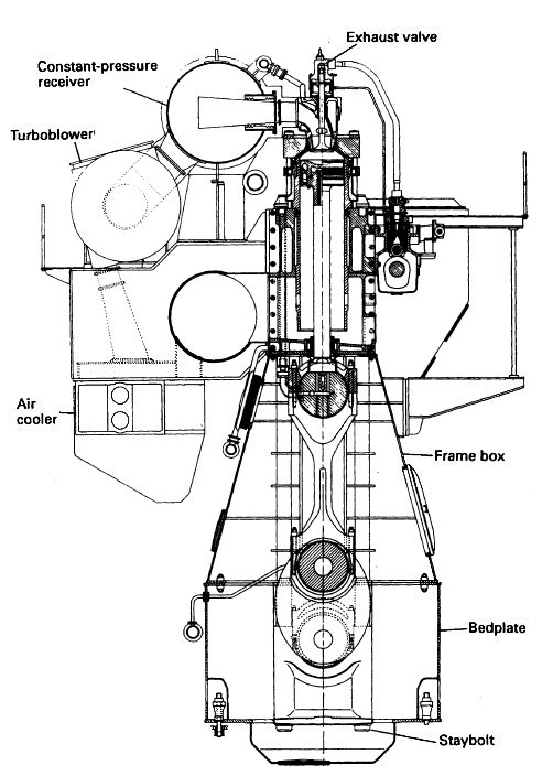
MAN B&W engine
Fig: MAN B&W L70MC engine

Particular attention must be paid to the balancing of cylinder loads in Diesel engines and to the tightness of holding down bolts on all reciprocating machinery. Full use must be made of all condition monitoring equipment supplied to detect and measure vibration, and any significant increase in vibration levels that cannot be accounted for must be reported to the management ashore.

Bedplate of the 7RT-flex60C engine with main bearing caps in place
Bedplate of the 7RT-flex60C engine

Fig: Bedplate of the 7RT-flex60C engine with main bearing caps in place (Photo courtesy of Wärtsilä Corporation)

Warming Through

Main engines are to be warmed through gradually following a stay in port or other occasion when they have been shut down. The jacket water circulation temperature is to be raised over a period of time to as near to the operating temperature as possible. The period of time is dependent on the jacket water temperature prior to the commencement of circulation, the heating medium and size of main engine etc. As a general rule circulation should commence not less than 12 hours before the estimated time of departure. Other circulating systems are to be put on line during this period i.e.
Precautions Prior to Standby Departure

All circulating systems are to be as near as is possible normal operating parameters according to the manufacturer’s instructions for the engine type. On vessels where the engine or engines are directly coupled to the propeller or propellers, the Deck Officer of the watch or Duty Deck Officer is to be contacted and permission to turn the engine requested. Once the Deck Officer has confirmed that this can safely be carried out, then and only then can the engine be turned.

All the indicator cocks are to be opened. The engine is then to be turned a minimum of one revolution with the turning gear during which time the indicator cocks are to be sighted for any evidence of oil or water discharge. If this test is satisfactory, then the indicator cocks are to be shut and the turning gear disengaged. It is of the utmost importance that the disengagement of the turning gear is physically checked. No reliance is to be placed on the indicator light in the control room, interlocks etc. It is the Chief Engineer’s responsibility to ensure that this physical check is carried out.

On vessels where the engine or engines are directly coupled to the propeller or propellers, the Deck Officer of the watch or Duty Deck Officer is to be contacted and permission to turn the engine on air requested. Once the Deck Officer has confirmed that this can safely be done, then and only then can the engine be turned on air. All indicator cocks are to be opened. In conjunction with the Bridge and as applicable, the engine is to be "kicked" ahead and astern on starting air. The indicator cocks are then to be closed.

Following the satisfactory turning of the engine on air, the Deck Officer of the watch is to be contacted and permission to turn the engine on fuel requested. Once the Deck Officer has confirmed that this can safely be done then, and only then, can the engine be turned on fuel. In conjunction with the Bridge the engine is to be turned dead slow ahead and astern on fuel.


Operation on Heavy Fuel Oil

Main engines designed to manoeuvre on heavy fuel oil are to be operated according to the manufacturer’s instructions. In the event of problems during manoeuvring on engines using heavy oil there must be no hesitation in changing over to diesel oil irrespective of whether the engines are being operated using bridge control, or using engine room control.

It is the Chief Engineer's responsibility to inform the Master of the particular engine type’s maximum period that it can safely remain in the stopped position. He is also to inform the Master of the procedures which will have to be carried out if the particular engine type’s maximum period at standstill during manoeuvring is exceeded.


Preparations for standby

1. Before a large diesel is started it must be warmed through by circulating hot water through the jackets, etc. This will enable the various engine parts to expand in relation to one another.

2. The various supply tanks, filters, valves and drains are all to be checked.

3. The lubricating oil pumps and circulating water pumps are started and all the visible returns should be observed.

4. All control equipment and alarms should be examined for correct operation.

5. The indicator cocks are opened, the turning gear engaged and the engine turned through several complete revolutions. In this way any water which may have collected in the cylinders will be forced out.

6. The fuel oil system is checked and circulated with hot oil.

7. Auxiliary scavenge blowers, if manually operated, should be started.

8. The turning gear is removed and if possible the engine should be turned over on air before closing the indicator cocks.

9. The engine is now available for standby.

The length of time involved in these preparations will depend upon the size of the engine.


Engine starting

1. The direction handle is positioned ahead or astern. This handle may be built into the telegraph reply lever. The camshaft is thus positioned relative to the crankshaft to operate the various cams for fuel injection, valve operation, etc.

2. The manoeuvring handle is moved to 'start'. This will admit compressed air into the cylinders in the correct sequence to turn the engine in the desired direction.A separate air start button may be used.

3. When the engine reaches its firing speed the manoeuvring handle is moved to the running position. Fuel is admitted and the combustion process will accelerate the engine and starting air admission will cease.


Engine reversing

When running at manoeuvring speeds:

1. Where manually operated auxiliary blowers are Fitted they should be started.

2. The fuel supply is shut off and the engine will quickly slow down,

3. The direction handle is positioned astern.

4. Compressed air is admitted to the engine to turn it in the astern direction.

5. When turning astern under the action of compressed air, fuel will be admitted. The combustion process will take over and air admission cease.


When running at full speed:

1. The auxiliary blowers, where manually operated, should be started.

2. Fuel is shut off from the engine.

3. Blasts of compressed air may be used to slow the engine down.

4. When the engine is stopped the direction handle is positioned astern.

5. Compressed air is admitted to turn the engine astern and fuel is admitted to accelerate the engine. The compressed air supply will then cease.


Marine diesel engine related other useful articles:
  1. Four stroke cycle diesel engines operational guideline

  2. The four-stroke cycle is completed in four strokes of the piston, or two revolutions of the crankshaft. In order to operate this cycle the engine requires a mechanism to open and close the inlet and exhaust valves
    More .....

  3. Two stroke cycle diesel engines operational guideline

  4. The two-stroke cycle is completed in two strokes of the piston or one revolution of the crankshaft. In order to operate this cycle where each event is accomplished in a very short time, the engine requires a number of special arrangements.
    More .....

  5. Power measurement for marine diesel engine - The engine indicator

  6. There are two possible measurements of engine power: the indicated power and the shaft power. The indicated power is the power developed within the engine cylinder and can be measured by an engine indicator. The shaft power is the power available at the output shaft of the engine and can be measured using a torsionmeter or with a brake.
    More .....

  7. Supply of fresh air and removal of exhaust gases by a gas exchanger

  8. A basic part of the cycle of an internal combustion engine is the supply of fresh air and removal of exhaust gases. This is the gas exchange process. Scavenging is the removal of exhaust gases by blowing in fresh air.
    More .....

  9. The fuel oil system for a diesel engine

  10. The fuel oil system for a diesel engine can be considered in two parts—the fuel supply and the fuel injection systems. Fuel supply deals with the provision of fuel oil suitable for use by the injection system.
    More .....

  11. Lubricating oil system for a marine diesel engine - how it works

  12. The lubrication system of an engine provides a supply of lubricating oil to the various moving parts in the engine. Its main function is to enable the formation of a film of oil between the moving parts, which reduces friction and wear. The lubricating oil is also used as a cleaner and in some engines as a coolant.
    More .....

  13. Cooling of ships engine - how it works , requirement of fresh water & sea water cooling system

  14. Cooling of engines is achieved by circulating a cooling liquid around internal passages within the engine. The cooling liquid is thus heated up and is in turn cooled by a sea water circulated cooler. Without adequate cooling certain parts of the engine which are exposed to very high temperatures, as a result of burning fuel, would soon fail.
    More .....

  15. Starting air system for diesel engine - how it works

  16. Diesel engines are started by supplying compressed air into the cylinders in the appropriate sequence for the required direction. A supply of compressed air is stored in air reservoirs or 'bottles' ready for immediate use. Up to 12 starts are possible with the stored quantity of compressed air.
    More .....

  17. Governor-Function of governors controlling speed of marine diesel engine

  18. The principal control device on any engine is the governor. It governs or controls the engine speed at some fixed value while power output changes to meet demand. This is achieved by the governor automatically adjusting the engine fuel pump settings to meet the desired load at the set speed.
    More .....

  19. Cylinder relief valve of a marine diesel engine - operational guideline

  20. The cylinder relief valve is designed to relieve pressures in excess of 10% to 20% above normal. The operation of this device indicates a fault in the engine which should be discovered and corrected.
    More .....

  21. Explosion relief valve of a marine diesel engine

  22. As a practical safeguard against explosions which occur in a crankcase, explosion relief valves or doors are fitted. These valves serve to relieve excessive crankcase pressures and stop flames being emitted from the crankcase. They must also be self closing to stop the return of atmospheric air to the crankcase.
    More .....

  23. Turning gear operational guideline
    The turning gear or turning engine is a reversible electric motor which drives a worm gear which can be connected with the toothed flywheel to turn a large diesel. A slow-speed drive is thus provided to enable positioning of the engine parts for overhaul purposes.
    More .....

  24. Couplings, clutches and gearboxes of a marine diesel engine

  25. The principal control device on any engine is the governor. It governs or controls the engine speed at some fixed value while power output changes to meet demand. This is achieved by the governor automatically adjusting the engine fuel pump settings to meet the desired load at the set speed.
    More .....

  26. MAN B&W diesel engine - Basic principles and operational guideline

  27. It is one of the MC series introduced in 1982, and has a longer stroke and increased maximum pressure when compared with the earlier L-GF and L-GB designs.
    More .....

  28. Crankcase oil mist detector of a marine diesel engine

  29. It is one of the MC series introduced in 1982, and has a longer stroke and increased maximum pressure when compared with the earlier L-GF and L-GB designs.
    More .....

  30. Various Heat exchanger for running machinery on board cargo ships

  31. Shell and tube heat exchangers for engine cooling water and lubricating oil cooling have traditionally been circulated with sea water. The sea water is in contact with the inside of the tubes, tube plates and water boxes.
    More .....

  32. Guideline for Turbochargers safety and operational requirement

  33. Shell and tube heat exchangers for engine cooling water and lubricating oil cooling have traditionally been circulated with sea water. The sea water is in contact with the inside of the tubes, tube plates and water boxes.
    More .....

  34. Function of Piston & piston rings

  35. Piston forms the lower part of the combustion chamber. It seals the cylinder and transmits the gas pressure to the connecting rod. The Piston comprises of two pieces; the crown and the skirt.The crown of a piston is subject to mechanical and thermal stresses.
    More .....


Machinery Spaces.com is about working principles, construction and operation of all the machinery items in a ship intended primarily for engineers working on board and those who working ashore . For any remarks please Contact us

Copyright © 2010-2016 Machinery Spaces.com All rights reserved.
Terms and conditions of use
Read our privacy policy|| Home page||