Machinery Spaces
Home || Diesel Engines ||Boilers||Feed Systems ||Steam Turbines ||Fuel Treatment ||Pumps ||Refrigeration ||

Couplings, Clutches and Gearboxes for Marine Diesel Engine

The diesel engine is a type of internal combustion engine which ignites the fuel by injecting it into hot, high-pressure air in a combustion chamber. In common with all internal combustion engines the diesel engine operates with a fixed sequence of events, which may be achieved either in four strokes or two, a stroke being the travel of the piston between its extreme points. Each stroke is accomplished in half a revolution of the crankshaft.

ships machinery spaces
container ships machinery info
Where the shaft speed of a medium-speed diesel engine is not suitable for its application, e.g. where a low speed drive for a propeller is required, a gearbox must be provided. Between the engine and gearbox it is usual to fit some form of flexible coupling to dampen out vibrations. There is also often a need for a clutch to disconnect the engine from the gearbox.

Couplings
Elastic or flexible couplings allow slight misalignment and damp out or remove torque variations from the engine. The coupling may in addition function as a clutch or disconnecting device.

Couplings may be mechanical, electrical, hydraulic or pneumatic in operation. It is usual to combine the function of clutch with a coupling and this is not readily possible with the mechanical coupling.

hydraulic coupling

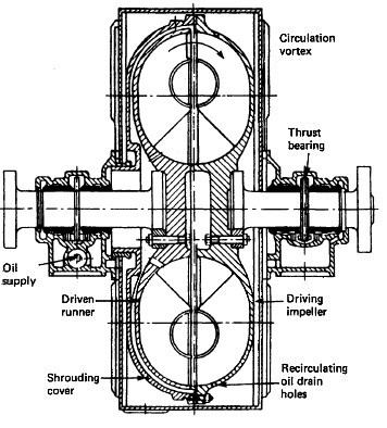
Fig: Hydraulic couplings


Plate type clutch

Fig: Plate type clutch

Clutches

A clutch is a device to connect or separate a driving unit from the unit it drives. With two engines connected to a gearbox a clutch enables one or both engines to be run, and facilitates reversing of the engine.

The hydraulic or fluid coupling uses oil to connect the driving section or impeller with the driven section or runner . No wear will thus take place between these two, and the clutch operates smoothly. The runner and impeller have pockets that face each other which are filled with oil as they rotate. The engine driven impeller provides kinetic energy to the oil which transmits the drive to the runner. Thrust bearings must be provided on either side of the coupling because of the axial thrust developed by this coupling.

A plate-type clutch consists of pressure plates and clutch plates arranged in a clutch spider . A forward and an aft clutch assembly are provided, and an externally mounted selector valve assembly is the control device which hydraulically engages the desired clutch. The forward clutch assembly is made up of the input shaft and the forward clutch spider. The input shaft includes the forward driven gear and, at its extreme end, a hub with the steel pressure plates of the forward clutch assembly spline-connected, i.e. free to slide. Thus when the input shaft turns, the forward driven gear and the forward clutch pressure plates will rotate. The forward clutch plates are positioned between the pressure plates and are spline-connected to the forward clutch spider or housing. This forward clutch spider forms part of the forward pinion assembly which surrounds but does not touch the input shaft.

The construction of the reverse clutch spider is similar. Both the forward and reverse pinions are in constant mesh with the output gear wheel which rotates the output shaft. In the neutral position the engine is rotating the input shaft and both driven gear wheels, but not the output shaft. When the clutch selector valve is moved to the ahead position, a piston assembly moves the clutch plates and pressure plates into contact. A friction grip is created between the smooth pressure plate and the clutch plate linings and the forward pinion rotates.

The forward pinion drives the output shaft and forward propulsion will occur. The procedure when the selector valve is moved to the astern position is similar but now the reverse pinion drives the output shaft in the opposite direction.


Gearboxes

The gearing arrangement used to reduce the medium-speed engine drive down to suitable propeller revolutions is always single reduction and usually single helical. Reduction ratios range from about 2:1 to 4:1 on modern installations.


Thrust Block

The clearances between the thrust pads and the thrust collar must be checked at intervals not exceeding those recommended by the component manufacturer. Where there are no manufacturer’s instructions this interval should not exceed 12 months, unless instructed otherwise by the management office.

The condition of the thrust collar surfaces must also be noted. With thrust blocks having a separate lubrication arrangement (i.e. not connected with the main lubrication system) the condition of the oil must be watched and the sump must be cleaned out when any signs of sludge are present. The condition of the cooling coils fitted in the sump must also be checked, and noted. The oil pressure alarms and filters, if any are fitted, must also be kept in good order.


Shaft Bearings

The oil in the propeller shaft bearings must be kept in good condition and the cooling water connections kept in good working order. If any of these bearings tend to overheat, a note to this effect should be made in the log book.


Main Engine Bracing

Main Engine top or side bracing is to be examined at regular intervals and the result of the inspection to be recorded in the Planned Maintenance System. Any damage to the bracing attachment or mechanism is to be reported to the relevant Management Office.


Marine diesel engine related other useful articles:
  1. Four stroke cycle diesel engines operational guideline

  2. The four-stroke cycle is completed in four strokes of the piston, or two revolutions of the crankshaft. In order to operate this cycle the engine requires a mechanism to open and close the inlet and exhaust valves
    More .....

  3. Two stroke cycle diesel engines operational guideline

  4. The two-stroke cycle is completed in two strokes of the piston or one revolution of the crankshaft. In order to operate this cycle where each event is accomplished in a very short time, the engine requires a number of special arrangements.
    More .....

  5. Power measurement for marine diesel engine - The engine indicator

  6. There are two possible measurements of engine power: the indicated power and the shaft power. The indicated power is the power developed within the engine cylinder and can be measured by an engine indicator. The shaft power is the power available at the output shaft of the engine and can be measured using a torsionmeter or with a brake.
    More .....

  7. Supply of fresh air and removal of exhaust gases by a gas exchanger

  8. A basic part of the cycle of an internal combustion engine is the supply of fresh air and removal of exhaust gases. This is the gas exchange process. Scavenging is the removal of exhaust gases by blowing in fresh air.
    More .....

  9. The fuel oil system for a diesel engine

  10. The fuel oil system for a diesel engine can be considered in two parts—the fuel supply and the fuel injection systems. Fuel supply deals with the provision of fuel oil suitable for use by the injection system.
    More .....

  11. Lubricating oil system for a marine diesel engine - how it works

  12. The lubrication system of an engine provides a supply of lubricating oil to the various moving parts in the engine. Its main function is to enable the formation of a film of oil between the moving parts, which reduces friction and wear. The lubricating oil is also used as a cleaner and in some engines as a coolant.
    More .....

  13. Cooling of ships engine - how it works , requirement of fresh water & sea water cooling system

  14. Cooling of engines is achieved by circulating a cooling liquid around internal passages within the engine. The cooling liquid is thus heated up and is in turn cooled by a sea water circulated cooler. Without adequate cooling certain parts of the engine which are exposed to very high temperatures, as a result of burning fuel, would soon fail.
    More .....

  15. Starting air system for diesel engine - how it works

  16. Diesel engines are started by supplying compressed air into the cylinders in the appropriate sequence for the required direction. A supply of compressed air is stored in air reservoirs or 'bottles' ready for immediate use. Up to 12 starts are possible with the stored quantity of compressed air.
    More .....

  17. Governor-Function of governors controlling speed of marine diesel engine

  18. The principal control device on any engine is the governor. It governs or controls the engine speed at some fixed value while power output changes to meet demand. This is achieved by the governor automatically adjusting the engine fuel pump settings to meet the desired load at the set speed.
    More .....

  19. Cylinder relief valve of a marine diesel engine - operational guideline

  20. The cylinder relief valve is designed to relieve pressures in excess of 10% to 20% above normal. The operation of this device indicates a fault in the engine which should be discovered and corrected.
    More .....

  21. Explosion relief valve of a marine diesel engine

  22. As a practical safeguard against explosions which occur in a crankcase, explosion relief valves or doors are fitted. These valves serve to relieve excessive crankcase pressures and stop flames being emitted from the crankcase. They must also be self closing to stop the return of atmospheric air to the crankcase.
    More .....

  23. Turning gear operational guideline
    The turning gear or turning engine is a reversible electric motor which drives a worm gear which can be connected with the toothed flywheel to turn a large diesel. A slow-speed drive is thus provided to enable positioning of the engine parts for overhaul purposes.
    More .....

  24. Couplings, clutches and gearboxes of a marine diesel engine

  25. The principal control device on any engine is the governor. It governs or controls the engine speed at some fixed value while power output changes to meet demand. This is achieved by the governor automatically adjusting the engine fuel pump settings to meet the desired load at the set speed.
    More .....

  26. MAN B&W diesel engine - Basic principles and operational guideline

  27. It is one of the MC series introduced in 1982, and has a longer stroke and increased maximum pressure when compared with the earlier L-GF and L-GB designs.
    More .....

  28. Crankcase oil mist detector of a marine diesel engine

  29. It is one of the MC series introduced in 1982, and has a longer stroke and increased maximum pressure when compared with the earlier L-GF and L-GB designs.
    More .....

  30. Various Heat exchanger for running machinery on board cargo ships

  31. Shell and tube heat exchangers for engine cooling water and lubricating oil cooling have traditionally been circulated with sea water. The sea water is in contact with the inside of the tubes, tube plates and water boxes.
    More .....

  32. Guideline for Turbochargers safety and operational requirement

  33. Shell and tube heat exchangers for engine cooling water and lubricating oil cooling have traditionally been circulated with sea water. The sea water is in contact with the inside of the tubes, tube plates and water boxes.
    More .....

  34. Function of Piston & piston rings

  35. Piston forms the lower part of the combustion chamber. It seals the cylinder and transmits the gas pressure to the connecting rod. The Piston comprises of two pieces; the crown and the skirt.The crown of a piston is subject to mechanical and thermal stresses.
    More .....


Marine machineries - Useful tags

Marine diesel engines ||Steam generating plant ||Air conditioning system ||Compressed air ||Marine batteries ||Cargo refrigeration ||Centrifugal pump ||Various coolers ||Emergency power supply ||Exhaust gas heat exchangers ||Feed system ||Feed extraction pump || Flow measurement || Four stroke engines || Fuel injector || Fuel oil system || Fuel oil treatment ||Gearboxes || Governor || Marine incinerator || Lub oil filters || MAN B&W engine || Marine condensers || Oily water separator || Overspeed protection devices || Piston & piston rings || Crankshaft deflection || Marine pumps || Various refrigerants || Sewage treatment plant || Propellers || Power Plants || Starting air system || Steam turbines || Steering gear || Sulzer engine || Turbine gearing || Turbochargers || Two stroke engines || UMS operations || Drydocking & major repairs || Critical machinery || Deck machineries & cargo gears || Control and instrumentation ||Fire protection ||Engine room safety ||


Machinery Spaces.com is about working principles, construction and operation of all the machinery items in a ship intended primarily for engineers working on board and those who working ashore . For any remarks please Contact us

Copyright © 2010-2016 Machinery Spaces.com All rights reserved.
Terms and conditions of use
Read our privacy policy|| Home page||