Machinery Spaces
Home || Diesel Engines ||Boilers||Feed Systems ||Steam Turbines ||Fuel Treatment ||Pumps ||Refrigeration ||

Fuel Oil System for Marine Diesel Engine

The fuel oil system for a marine diesel engine can be considered in two parts—the fuel supply and the fuel injection systems. Fuel supply deals with the provision of fuel oil suitable for use by the injection system. Marine Fuel oil system includes various piping systems provided for bunkering, storage, transfer, offloading and treatment of fuel oils.

Fuel oil transfer system – This system receives and stores fuel and delivers it to settling tanks. Fuel oils are loaded through deck fill connections that have sample connections provided to permit the fuel to be sampled as it is taken aboard. HFO is loaded in storage tanks fitted with heating coils.

ships machinery spaces
container ships machinery info
In preparation for use, HFO is transferred to the fuel oil settling tanks via FO transfer pumps which are equipped with a suction strainer. Piping is so arranged that the pumps can transfer fuel between storage tanks and then to the deck connections for offloading. Settling tanks are used to permit gross water and solids to settle on the bottom.

Fuel tank overflow system : All tanks overflow to an overflow tank via a line w ith an observation glass. This line also incorporates a flow alarm. Fitted in the overflow tank is a level alarm which will be activated when the tank is a quarter full.

All tank vents are fitted so that oil cannot overflow onto deck or into machinery spaces which may lead to fires. The vent from the overflow tank is led onto deck and fitted with wire gauze diaphragms.

Fuel oil supply for a two-stroke diesel engine: A slow-speed two-stroke diesel is usually arranged to operate continuously on heavy fuel and have available a diesel oil supply for manoeuvring conditions.

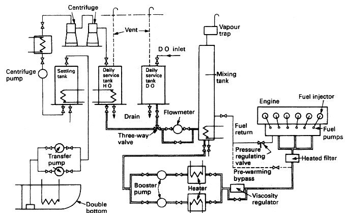
In the system shown in Figure , the oil is stored in tanks in the double bottom from which it is pumped to a settling tank and heated. After passing through centrifuges the cleaned, heated oil is pumped to a daily service tank. From the daily service tank the oil flows through a three-way valve to a mixing tank. A flow meter is fitted into the system to indicate fuel consumption. Booster pumps are used to pump the oil through heaters and a viscosity regulator to the engine-driven fuel pumps. The fuel pumps will discharge high-pressure fuel to their respective injectors.

The viscosity regulator controls the fuel oil temperature in order to provide the correct viscosity for combustion. A pressure regulating valve ensures a constant-pressure supply to the engine-driven pumps, and a pre-warming bypass is used to heat up the fuel before starting the engine.

A diesel oil daily service tank may be installed and is connected to the system via a three-way valve. The engine can be started up and manoeuvred on diesel oil or even a blend of diesel and heavy fuel oil. The mixing tank is used to collect recirculated oil and also acts as a buffer or reserve tank as it will supply fuel when the daily service tank is empty.

Fuel oil system for cargo ships
Fig : Fuel oil system for cargo ships

The system includes various safety devices such as low-level alarms and remotely operated tank outlet valves which can be closed in the event of a fire.

Operation on Heavy Fuel Oil

Main engines designed to manoeuvre on heavy fuel oil are to be operated according to the manufacturer’s instructions. All other types of main engines are to be manoeuvred on diesel oil according to the manufacturers’ instructions.

In the event of problems during manoeuvring on engines using heavy oil there must be no hesitation in changing over to diesel oil irrespective of whether the engines are being operated using bridge control, or using engine room control.

It is the Chief Engineer's responsibility to inform the Master of the particular engine type’s maximum period that it can safely remain in the stopped position. He is also to inform the Master of the procedures which will have to be carried out if the particular engine type’s maximum period at standstill during manoeuvring is exceeded.


Fuel injection

The function of the fuel injection system is to provide the right amount of fuel at the right moment and in a suitable condition for the combustion process. There must therefore be some form of measured fuel supply, a means of timing the delivery and the atomisation of the fuel. The injection of the fuel is achieved by the location of cams on a camshaft. This camshaft rotates at engine speed for a two-stroke engine and at half engine speed for a four-stroke. There are two basic systems in use, each of which employs a combination of mechanical and hydraulic operations. The most common system is the jerk pump; the other is the common rail.

Various safety devices in a fuel system for a diesel engine are:
  1. Quick closing valves on settling/service tanks
  2. relief valves on 2 pumps/heaters
  3. quick closing valve on mixing/vent tank
  4. pipes lagged/save-alls under pumps and heaters
  5. low fuel oil pressure alarm
  6. high fuel oil pressure alarm
  7. low fuel oil temperature alarm
  8. high fuel oil temperature alarm
  9. emergency remote stops for pumps
  10. high pressure pipes between fuel injection pump and injector are double skinned.


Pipes carrying fuel oil and flammable liquids

There are two principal types of pipes that carry fuel and they are categorised by the pressure the pipe is designed to withstand. Low-pressure pipes are used to move fuel from a storage tank to a service tank to an injection pump; high-pressure pipes are used to deliver fuel from an injection pump to an engine combustion chamber. Ships’ fuel is usually stored in double-bottom tanks, deep tanks, side bunker tanks, settling tanks or service tanks. Piping between a service tank and a fuel transfer or booster pump is rated as low pressure. However, between each pumping stage, pressure increases.

It is a mistake to assume that even if a pipe’s pressure is relatively low, fuel will not spray from a crack or small hole. Pipes from fuel tanks can pass through ballast tanks and pipes serving ballast tanks can pass through fuel tanks. Because of pollution risks, classification societies have stringent rules restricting the length of any oil pipe passing through a ballast tank (and vice versa); it must be short, have increased wall thickness and stronger flanges.

The Safety of Life at Sea Convention (SOLAS) includes requirements for fire safety in engine rooms. In particular, special double-skinned pipes must be used to deliver fuel to engine combustion chambers. These are made of low carbon steel alloys and operate at high pressure, between 600 and 900 bar. Double skins are necessary because pipe fracture will cause fuel to spray in a fine aerosol.

Fuel will ignite on contact with a hot surface, such as a turbocharger casing or exhaust pipe. The second skin is to guard against direct spraying. The pipe is designed so that fuel will be contained in the space between the outer skin and the main pipe, and will drain into a collecting tank fitted with a high-level alarm.

Low-pressure lubricating and fuel oil pipes passing close to a hot surface have to be secured against the possibility of oil spraying from a flange. To prevent this, the flange is usually taped. In addition, and whenever possible, the pipes are routed clear of hot surfaces. Similarly, to prevent leaking oil falling onto a hot surface, pipes should never be allowed to run above a hot surface. Regular thermographic surveys of hot surfaces will identify those risk areas that are sufficiently hot to ignite spraying or leaking fuel. Preventive measures to be taken include additional lagging, spray or drip shields.

Two reasons why fuel pipes should be clipped and supported are to prevent stress and fractures from vibration.

Fuel oil transfer pipes are usually mild steel and may corrode. The calculation for minimum wall thickness includes a small allowance for corrosion. As a pipe ages and corrodes, leakage can occur. Inspection programmes should concentrate on identifying worn or corroded pipes.


Related Information:

Marine diesel engine related other useful articles:
  1. Four stroke cycle diesel engines operational guideline

  2. The four-stroke cycle is completed in four strokes of the piston, or two revolutions of the crankshaft. In order to operate this cycle the engine requires a mechanism to open and close the inlet and exhaust valves
    More .....

  3. Two stroke cycle diesel engines operational guideline

  4. The two-stroke cycle is completed in two strokes of the piston or one revolution of the crankshaft. In order to operate this cycle where each event is accomplished in a very short time, the engine requires a number of special arrangements.
    More .....

  5. Power measurement for marine diesel engine - The engine indicator

  6. There are two possible measurements of engine power: the indicated power and the shaft power. The indicated power is the power developed within the engine cylinder and can be measured by an engine indicator. The shaft power is the power available at the output shaft of the engine and can be measured using a torsionmeter or with a brake.
    More .....

  7. Supply of fresh air and removal of exhaust gases by a gas exchanger

  8. A basic part of the cycle of an internal combustion engine is the supply of fresh air and removal of exhaust gases. This is the gas exchange process. Scavenging is the removal of exhaust gases by blowing in fresh air.
    More .....

  9. The fuel oil system for a diesel engine

  10. The fuel oil system for a diesel engine can be considered in two parts—the fuel supply and the fuel injection systems. Fuel supply deals with the provision of fuel oil suitable for use by the injection system.
    More .....

  11. Lubricating oil system for a marine diesel engine - how it works

  12. The lubrication system of an engine provides a supply of lubricating oil to the various moving parts in the engine. Its main function is to enable the formation of a film of oil between the moving parts, which reduces friction and wear. The lubricating oil is also used as a cleaner and in some engines as a coolant.
    More .....

  13. Cooling of ships engine - how it works , requirement of fresh water & sea water cooling system

  14. Cooling of engines is achieved by circulating a cooling liquid around internal passages within the engine. The cooling liquid is thus heated up and is in turn cooled by a sea water circulated cooler. Without adequate cooling certain parts of the engine which are exposed to very high temperatures, as a result of burning fuel, would soon fail.
    More .....

  15. Starting air system for diesel engine - how it works

  16. Diesel engines are started by supplying compressed air into the cylinders in the appropriate sequence for the required direction. A supply of compressed air is stored in air reservoirs or 'bottles' ready for immediate use. Up to 12 starts are possible with the stored quantity of compressed air.
    More .....

  17. Governor-Function of governors controlling speed of marine diesel engine

  18. The principal control device on any engine is the governor. It governs or controls the engine speed at some fixed value while power output changes to meet demand. This is achieved by the governor automatically adjusting the engine fuel pump settings to meet the desired load at the set speed.
    More .....

  19. Cylinder relief valve of a marine diesel engine - operational guideline

  20. The cylinder relief valve is designed to relieve pressures in excess of 10% to 20% above normal. The operation of this device indicates a fault in the engine which should be discovered and corrected.
    More .....

  21. Explosion relief valve of a marine diesel engine

  22. As a practical safeguard against explosions which occur in a crankcase, explosion relief valves or doors are fitted. These valves serve to relieve excessive crankcase pressures and stop flames being emitted from the crankcase. They must also be self closing to stop the return of atmospheric air to the crankcase.
    More .....

  23. Turning gear operational guideline
    The turning gear or turning engine is a reversible electric motor which drives a worm gear which can be connected with the toothed flywheel to turn a large diesel. A slow-speed drive is thus provided to enable positioning of the engine parts for overhaul purposes.
    More .....

  24. Couplings, clutches and gearboxes of a marine diesel engine

  25. The principal control device on any engine is the governor. It governs or controls the engine speed at some fixed value while power output changes to meet demand. This is achieved by the governor automatically adjusting the engine fuel pump settings to meet the desired load at the set speed.
    More .....

  26. MAN B&W diesel engine - Basic principles and operational guideline

  27. It is one of the MC series introduced in 1982, and has a longer stroke and increased maximum pressure when compared with the earlier L-GF and L-GB designs.
    More .....

  28. Crankcase oil mist detector of a marine diesel engine

  29. It is one of the MC series introduced in 1982, and has a longer stroke and increased maximum pressure when compared with the earlier L-GF and L-GB designs.
    More .....

  30. Various Heat exchanger for running machinery on board cargo ships

  31. Shell and tube heat exchangers for engine cooling water and lubricating oil cooling have traditionally been circulated with sea water. The sea water is in contact with the inside of the tubes, tube plates and water boxes.
    More .....

  32. Guideline for Turbochargers safety and operational requirement

  33. Shell and tube heat exchangers for engine cooling water and lubricating oil cooling have traditionally been circulated with sea water. The sea water is in contact with the inside of the tubes, tube plates and water boxes.
    More .....

  34. Function of Piston & piston rings

  35. Piston forms the lower part of the combustion chamber. It seals the cylinder and transmits the gas pressure to the connecting rod. The Piston comprises of two pieces; the crown and the skirt.The crown of a piston is subject to mechanical and thermal stresses.
    More .....


Machinery Spaces.com is about working principles, construction and operation of all the machinery items in a ship intended primarily for engineers working on board and those who working ashore . For any remarks please Contact us

Copyright © 2010-2016 Machinery Spaces.com All rights reserved.
Terms and conditions of use
Read our privacy policy|| Home page||