Machinery Spaces
Home || Diesel Engines ||Boilers||Feed Systems ||Steam Turbines ||Fuel Treatment ||Pumps ||Refrigeration ||

Piping systems for cargo ship's machinery spaces

A ship's machinery space contains hundreds of metres of piping and fittings. The various systems are arranged to carry many different liquids at various temperatures and pressures. The influences of operational and safety requirements, as well as legislation, result in somewhat complicated arrangements of what are a few basic fittings. Valves, strainers, branch pipes, etc., are examples of fittings which are found in a pipe system.
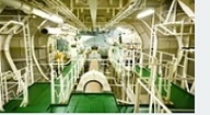
ships machinery spaces
container ships machinery info
Pipes: Machinery space pipework is made up of assorted straight lengths and bends joined by flanges with an appropriate gasket or joint between, or very small-bore piping may use compression couplings. The piping material will be chosen to suit the liquid carried and the system conditions. Some examples are shown below .

Where piping is to be galvanised, the completed pipe with all joints fully welded is to be hot dipped galvanised. The pipes are supported and held in by hangers or pipe clips in such a way as to minimise vibration. Steam pipes or pipes in systems with considerable temperature variation may be supported on spring hangers which permit a degree of movement. An alternative to spring hangers is the use of expansion loops of piping or an expansion joint.

Machinery spaces piping system - various fittings

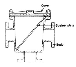
Mud boxes: Mud boxes are fitted into the machinery space bilge suction piping. The mud box is a coarse strainer with a straight tailpipe down to the bilge . To enable the internal perforated plate to be cleaned when necessary, the lid of the mud box is easily removed without disconnecting any pipework.

Suction pipes

Suction pipes in tanks should be arranged with a bell mouth or foot. The bell end or foot should provide an inlet area of about one-and-a-half times the pipe area.

It should also be a sufficient distance from the bottom plating and nearby structure to provide a free suction area, again about one-and-a-half times the pipe area.

Mud box

Fig:Mud box


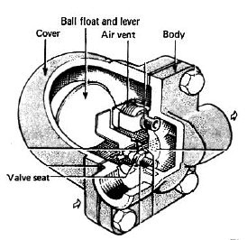
Steam traps

Steam trapFig:Steam trap

A steam trap does as its name implies and permits only the passage of condensed steam. It operates automatically and is situated in steam drain lines. Various designs are available utilising mechanical floats which, when floating in condensate, will enable the condensate to discharge . Other designs employ various types of thermostat to operate the valve which discharges the condensate.

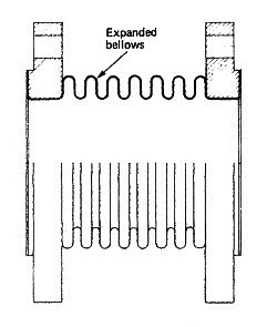
Expansion pieces

Expansion bellows pieceFig:An Expansion bellows piece

An expansion piece is fitted in a pipeline which is subject to considerable temperature variations. One type consists of a bellows arrangement which will permit movement in several directions and absorb vibration . The fitting must be selected according to the variation in system temperatures and installed to permit the expansion and contraction required in the system.


Drains

Drains are provided in pipelines and usually have small cocks to open or close them. It is essential that certain pipelines are drained regularly, particularly in steam systems. When steam is admitted to a pipeline containing a reasonable surface of water it will condense and a partial vacuum occur: the water will then be drawn along the pipe until it meets a bend or a closed valve. The impact of the moving water in the pipework will create large forces known as 'water hammer', which can result in damage to pipework and fittings.


Connection to pumps

Pipes are connected to pumps by flanges. Flanges are a potential weak point in a piping system. Occasionally, and to provide the correct pressure from a pump, a calibration orifice is fitted in the delivery piping. This can result in turbulent fluid flow and cause abrasive corrosion or erosion. Welded flanges are prone to accelerated corrosion in the weld metal or in the heat-affected zone. Pipes in wet areas where corrosion is likely need to be examined at regular intervals (six-monthly).

Pipe joints

The preferred method for connecting two lengths of steel pipe, whether a straight, elbow or tee joint, is with a flange. With the possible exception of small-bore pipes in low-pressure systems, pipes are not normally connected by threaded joints.

Mechanical, expansion or sliding joints are fitted in longitudinal pipes to allow the pipe to move when a ship bends and flexes, or to cater for thermal expansion. Expansion joints are not fitted where there is regularly high stress, nor are they used inside cargo holds or tanks. Expansion joints should never be used as a permanent connection for corroded pipes after a temporary repair. Classification society rules define which piping systems to use and the positions where expansion joints can be fitted. Only approved expansion joints are allowed.

Clips and supports

Clips and supports are used to hold pipes in position and to prevent movement or vibration. A vibrating pipe can ‘work harden’ and fail. Pipes can fracture when there is insufficient support.

There are no hard and fast rules about the number of clips required in a length of pipe as this will depend on the pipe’s diameter, length, its position and the density of fluid conveyed. The contact area at the surface of the pipe requires protection. Failures often occur as a result of mechanical wear when the clip loosens, allowing the pipe to move. Inspection procedures must be designed to ensure that all clips are checked regularly, including those hidden from sight behind insulation or under engine room floor plates. Special attention should be paid to clips in concealed places.

Valves

Valves are fitted to isolate sections of pipe and will typically be found at suction points, crossovers, feed lines, delivery lines and where pipes need to be removed. Valves connected to the shell are flanged and made of steel or other ductile material. Grey or nodular cast iron cannot be used for boiler blow-down valves, for valves fitted to fuel oil or lubricating oil tanks, or for shell valves. Shell valves should be tested regularly, on a monthly basis, by opening them. Marking valve handles with high-visibility paint will help with identification during an emergency.

Cast iron valves have a service life shorter than those made from cast steel. Consequently, they need careful examination during a special survey.


Machinery space pipework material

Waste steam :Carbon steel to BS 3601

SW circulating :Aluminium brass

Wash deck and firemain :Carbon steel to BS3601 — galvanised

Bilge and ballast :Carbon steel to BS3601 - galvanised

Control air :Copper

Starting air :Carbon steel to BS 3602

All system pipework throughout the vessel is to be periodically inspected for condition and security in a systematic manner and be reported upon in the PMS. It is of utmost importance to include in these inspections the pipework located in those spaces that are remote, poorly lit and may be difficult to access.

Particular attention should be paid to sea water pipework which may be subject to corrosion and wastage on both internal and external surfaces, and opportunity should be taken whenever possible, and certainly during drydocking periods, to establish pipewall condition by hammer testing and visual inspection of internal surfaces in locations where valves or pipe sections have been removed for routine maintenance, repair or replacement. Defective pipework is to be replaced at the earliest convenient opportunity.

Classification societies have specific requirements with regard to ships’ piping systems that follow the general survey criteria. The survey involves extensive examinations and checks to show that all piping systems are in satisfactory condition to allow the ship to operate and for the new period of class to be assigned (provided proper maintenance and required interim surveys are carried out).

Machinery and all piping systems used for essential services are examined and tested under working conditions, as considered necessary by the surveyor.

Steam pipes are specially examined. Superheated steam pipes with a steam temperature exceeding 450°C require additional tests.

Piping systems for fuel or lubricating oil are carefully examined.


Related Info:

  1. Various valves arrangement for machinery spaces piping system
  2. Straight-through cocks, Globe valve,Non-return valves,gate valves,Relief valves, quick closing valves, valve chests....

  3. Dealing with pipe failure and related guideline
  4. Pipes corrode internally and externally. Internally, they may be affected by erosion, uniform and abrasive corrosion, fatigue and galvanic action. Externally, corrosion is caused mainly by atmospheric conditions, but pipes can corrode locally where liquids drip onto them......

  5. Ships piping system maintenance tips
  6. It is important to identify failing pipes before leakage occurs; maintenance of piping is as much about procedural checks and pressure tests to locate weak points as it is about actual repair. .....

  7. Reciprocating displacement pumping system for ships use
  8. The displacement pumping action is achieved by the reduction or increase in volume of a space causing the liquid (or gas) to be physically moved. The method employed is either a piston in a cylinder using a reciprocating motion, or a rotating unit using vanes, gears or screws.

  9. Centrifugal pump principles and working procedure
  10. In a centrifugal pump liquid enters the centre or eye of the impeller and flows radially out between the vanes, its velocity being increased by the impeller rotation....

  11. How a pneumatically control valve works ?
  12. Many pneumatic devices use a nozzle and flapper system to give a variation in the compressed air signal.A typical pneumatic control valve is shown in Figure . It can be considered as made up of two parts—the actuator and the valve. A flexible diaphragm forms a pressure tight chamber in the upper half of the actuator and the controller signal is fed in.....

  13. Domestic water systems for general cargo ship
  14. Domestic water systems usually comprise a fresh water system for washing and drinking and a salt water system for sanitary purposes . Both use a basically similar arrangement of an automatic pump supplying the liquid to a tank which is pressurised by compressed air...

  15. Bilge and ballast systems for general cargo ships
  16. The bilge main is arranged to drain any watertight compartment other than ballast, oil or water tanks and to discharge the contents overboard. The number of pumps and their capacity depend upon the size, type and service of the vessel.....


Marine machineries - Useful tags

Marine diesel engines ||Steam generating plant ||Air conditioning system ||Compressed air ||Marine batteries ||Cargo refrigeration ||Centrifugal pump ||Various coolers ||Emergency power supply ||Exhaust gas heat exchangers ||Feed system ||Feed extraction pump || Flow measurement || Four stroke engines || Fuel injector || Fuel oil system || Fuel oil treatment ||Gearboxes || Governor || Marine incinerator || Lub oil filters || MAN B&W engine || Marine condensers || Oily water separator || Overspeed protection devices || Piston & piston rings || Crankshaft deflection || Marine pumps || Various refrigerants || Sewage treatment plant || Propellers || Power Plants || Starting air system || Steam turbines || Steering gear || Sulzer engine || Turbine gearing || Turbochargers || Two stroke engines || UMS operations || Drydocking & major repairs || Critical machinery || Deck machineries & cargo gears || Control and instrumentation ||Fire protection ||Engine room safety ||


Machinery Spaces.com is about working principles, construction and operation of all the machinery items in a ship intended primarily for engineers working on board and those who working ashore . For any remarks please Contact us

Copyright © 2010-2016 Machinery Spaces.com All rights reserved.
Terms and conditions of use
Read our privacy policy|| Home page||