Machinery Spaces
Home || Diesel Engines ||Boilers||Feed Systems ||Steam Turbines ||Fuel Treatment ||Pumps ||Refrigeration ||

Marine Reciprocating Displacement Pumps

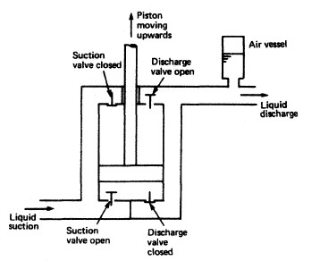
A pump is a machine used to raise liquids from a low point to a high point. The displacement pumping action is achieved by the reduction or increase in volume of a space causing the liquid (or gas) to be physically moved. The method employed is either a piston in a cylinder using a reciprocating motion, or a rotating unit using vanes, gears or screws. A reciprocating displacement pump is shown diagrammatically in figure here, to demonstrate the operating principle.
ships machinery spaces
container ships machinery info
The pump is double-acting, that is liquid is admitted to either side of the piston where it is alternately drawn in and discharged. As the piston moves upwards, suction takes place below the piston and liquid is drawn in, the valve arrangement ensuring that the discharge valve cannot open on the suction stroke. Above the piston, liquid is discharged and the suction valve remains closed. As the piston travels down, the operations of suction and discharge occur now on opposite sides.

An air vessel is usually fitted in the discharge pipework to dampen out the pressure variations during discharge. As the discharge pressure rises the air is compressed in the vessel, and as the pressure falls the air expands. The peak pressure energy is thus 'stored' in the air and returned to the system when the pressure falls. Air vessels are not fitted on reciprocating boiler feed pumps since they may introduce air into the de-aerated feedwater.

reciprocating-displacement-pumps

Fig: Reciprocating displacement pumping system on board


A relief valve is always fitted between the pump suction and discharge chambers to protect the pump should it be operated with a valve closed in the discharge line.

Reciprocating displacement pumps are self priming, will accept high suction lifts, produce the discharge pressure required by the system and can handle large amounts of vapour or entrained gases. They are, however, complicated in construction with a number of moving parts requiring attention and maintenance.

When starting the pump the suction and discharge valves must be opened. It is important that no valves in the discharge line are closed, otherwise either the relief valve will lift or damage may occur to the pump when it is started. The pump is self priming, but where possible to reduce wear or the risk of seizure it should be flooded with liquid before starting.

An electrically driven pump needs only to be switched on, when it will run erratically for a short period until liquid is drawn into the pump. A steam driven pump will require the usual draining and warming-through procedure before steam is gradually admitted. Most of the moving parts in the pump will require examination during overhaul. The pump piston, rings and cylinder liner must also be thoroughly checked. Ridges will eventually develop at the limits of the piston ring travel and these must be removed. The suction and discharge valves must be refaced or ground in as required.

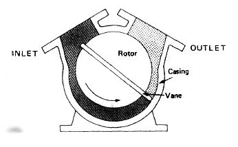
Two different rotary displacement pumps are shown in Figure , The action in each case results in the trapping of a quantity of liquid (or air) in a volume or space which becomes smaller at the discharge or outlet side. It should be noted that the liquid does not pass between the screw or gear teeth as they mesh but travels between the casing and the teeth.

The starting procedure is similar to that for the reciprocating displacement pump. Again a relief valve will be fitted between suction and discharge chambers. The particular maintenance problem with this type of pump is the shaft sealing where the gland and packing arrangement must be appropriate for the material pumped. The rotating vane type will suffer wear at a rate depending upon the liquid pumped and its freedom from abrasive or corrosive substances. The screw pump must be correcdy timed and if stripped for inspection care should be taken to assemble the screws correctly.

A special type of rotary displacement pump has a particular application in steering gear

rotary-vane-displacement-pump

Fig: Rotary vane displacement pumping system on board


Related Info:

  1. Various valves arrangement for machinery spaces piping system
  2. Straight-through cocks, Globe valve,Non-return valves,gate valves,Relief valves, quick closing valves, valve chests....

  3. Mud boxes, Suction pipes, Steam traps, Expansion pieces & Drains for Machinery space piping system
  4. The mud box is a coarse strainer with a straight tailpipe down to the bilge..Suction pipes in tanks should be arranged with a bell mouth or foot..An expansion piece is fitted in a pipeline which is subject to considerable temperature variations..Drains are provided in pipelines and usually have small cocks to open or close them.....

  5. Reciprocating displacement pumping system for ships use
  6. The displacement pumping action is achieved by the reduction or increase in volume of a space causing the liquid (or gas) to be physically moved. The method employed is either a piston in a cylinder using a reciprocating motion, or a rotating unit using vanes, gears or screws.

  7. Centrifugal pump principles and working procedure
  8. In a centrifugal pump liquid enters the centre or eye of the impeller and flows radially out between the vanes, its velocity being increased by the impeller rotation....

  9. How a pneumatically control valve works ?
  10. Many pneumatic devices use a nozzle and flapper system to give a variation in the compressed air signal.A typical pneumatic control valve is shown in Figure . It can be considered as made up of two parts—the actuator and the valve. A flexible diaphragm forms a pressure tight chamber in the upper half of the actuator and the controller signal is fed in.....

  11. Domestic water systems for general cargo ship
  12. Domestic water systems usually comprise a fresh water system for washing and drinking and a salt water system for sanitary purposes . Both use a basically similar arrangement of an automatic pump supplying the liquid to a tank which is pressurised by compressed air...

  13. Bilge and ballast systems for general cargo ships
  14. The bilge main is arranged to drain any watertight compartment other than ballast, oil or water tanks and to discharge the contents overboard. The number of pumps and their capacity depend upon the size, type and service of the vessel.....


Marine machineries - Useful tags

Marine diesel engines ||Steam generating plant ||Air conditioning system ||Compressed air ||Marine batteries ||Cargo refrigeration ||Centrifugal pump ||Various coolers ||Emergency power supply ||Exhaust gas heat exchangers ||Feed system ||Feed extraction pump || Flow measurement || Four stroke engines || Fuel injector || Fuel oil system || Fuel oil treatment ||Gearboxes || Governor || Marine incinerator || Lub oil filters || MAN B&W engine || Marine condensers || Oily water separator || Overspeed protection devices || Piston & piston rings || Crankshaft deflection || Marine pumps || Various refrigerants || Sewage treatment plant || Propellers || Power Plants || Starting air system || Steam turbines || Steering gear || Sulzer engine || Turbine gearing || Turbochargers || Two stroke engines || UMS operations || Drydocking & major repairs || Critical machinery || Deck machineries & cargo gears || Control and instrumentation ||Fire protection ||Engine room safety ||


Machinery Spaces.com is about working principles, construction and operation of all the machinery items in a ship intended primarily for engineers working on board and those who working ashore . For any remarks please Contact us

Copyright © 2010-2016 Machinery Spaces.com All rights reserved.
Terms and conditions of use
Read our privacy policy|| Home page||