Machinery Spaces
Home || Diesel Engines ||Boilers||Feed Systems ||Steam Turbines ||Fuel Treatment ||Pumps ||Refrigeration ||

Ships piping system- maintenance guideline

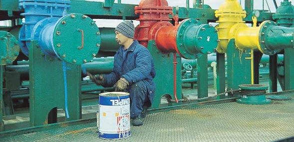
Unless they are made of non-corrosive material, are galvanised or plastic-coated, the external surfaces of pipes should be painted. Generally, the maintenance of pipes should concentrate on identifying and replacing those that have weakened.

It is important to identify failing pipes before leakage occurs; maintenance of piping is as much about procedural checks and pressure tests to locate weak points as it is about actual repair.
ships machinery spaces
container ships machinery info
The following inspection procedures are recommended:
  1. Inspect exposed piping and pipes in wet or damp locations at regular intervals as set down in the ship’s maintenance schedule. Look for breakdown of the protective coating. Check for frictional wear at pipe clips and expansion joints.


  2. Inspect the inside of pipes where they connect to pumps and refrigeration equipment; this might require the removal of a length of pipe. Look for cracks caused by erosion.


  3. Check bends and supports for fatigue corrosion that can occur when piping is subject to vibration. If a pipe does vibrate, fit additional clips or supports.


  4. Check the wall thickness along the outer part of a curved pipe that forms an expansion curve. Expansion curves are usually cold bent and have reduced thickness on the outer part of the bend. Erosion inside the pipe can cause accelerated thinning of the outer wall. Measure thickness with an ultrasonic meter. Check a pipe’s threaded connection where it is attached to a component made of different material. Look for galvanic corrosion.


  5. Check fixed expansion joints (bellows) for deformation. Look for distortion that can occur with overpressure. These joints are designed to withstand twice the pipe’s normal working pressure. Deformed bellows must be replaced.


  6. Check for localised leakage as this can give rise to accelerated corrosion. Inspect glands on valves fitted in saltwater ballast lines and seawater cooling pipes. Repair all leaks, irrespective of quantity. Remember that a slight leakage is needed to lubricate the valve stem.


  7. Open and close line valves at scheduled intervals, especially those that are used infrequently. Pay special attention to valves that connect to the shell.


  8. Repair paint coatings. Fit a doubler where the pipe has suffered frictional wear as a result of chafing contact with a support clip or clamp.


  9. Measure a pipe’s wall thickness and replace it if its corrosion allowance has been consumed.


  10. Remove lengths of insulation from steam pipes and check for corrosion. Repair or replace corroded pipes. When replacing insulation, refit with an external layer of waterproof material.


  11. Look for pitting when checking stainless steel piping especially if it carries saltwater. This is easily identified by the presence of small rusty points on the pipe’s exterior. If these are found, repair with a section of new pipe. A temporary repair can be made by chipping away the rust, cleaning the area/pipe with a stainless steel wire brush and painting it. Pitting is also likely occur on the pipe’s inner surface and its presence can be detected by removing a section of pipe and checking visually.


  12. Co-ordinate visual examinations with pressure tests. Some operators prefer to pressure test before a visual examination. Pressure tests should be arranged after a pipe has received an impact, even if visually there is no obvious damage. When carrying out an hydraulic test, which is a pressure test using water, apply a pressure equal to 1.5 times the pipe’s working pressure. Before the test, isolate ball valves to avoid accidental damage to valve seals. Use a pressure test to reveal small cracks, holes, and leakages at flanges or at other connections.


  13. Whenever accelerated corrosion or advanced thinning of a pipe is found, check all similar pipes in similar locations since they are likely to be affected, too.


  14. If a particular space needs regular bilge pumping, it indicates leakage. Check the space thoroughly to identify the leak. Pipes that fail are not normally repaired – they are replaced. If there is a need for local repair, then treat it as a temporary repair.


  15. Temporary repairs can be made by using binding and rubber, cement blocks, rings and clamps, or plastic resin. Wooden plugs in conjunction with binding are occasionally used to plug a holed pipe.

  16. Oil tanker cargo piping arrangement
    Fig: Oil tanker cargo piping arrangement


  17. Permanent repairs usually involve the removal and replacement of a length of piping. Welded doublers are not acceptable as a permanent repair.


  18. A permanent repair can only be done with classification society approved material. The society’s rules require the repair to be examined and approved by its surveyor. After making any repairs, do a pressure test and a nondestructive test of any welded connection using the dye penetration procedure.


  19. After completing any repair, refit pipe supports or clips. Use additional supports if the pipe moves or vibrates.


  20. Replace spray shields on pipes that carry flammable liquids, especially if the pipe is located near a hot surface.


  21. Slag can fall inside pipes joined by welding and cause a blockage or clog valve seats. Flush the pipe before use.


  22. After repairing lubricating oil or hydraulic pipes, seek the equipment maker’s advice on the care of oil and filters.


Oil tanker cargo pipes color coding
Fig: Oil tanker cargo pipes color coding

DO’S AND DON’TS

ALWAYS DO:
NEVER:
PRESSURE TEST PROCEDURE

A hydraulic pressure test is a straightforward shipboard operation. Follow these guidelines:
  1. Isolate the area where piping is to be tested.


  2. Fill piping with water, taking care to eliminate all possible air pockets that remain in the pipe before raising the pressure.


  3. Increase the pressure in the pipes slowly, making sure that shock loading is avoided. Watch out for problems as the pressure increases.


  4. When the maximum pressure is reached, maintain that pressure for between 15 and 30 minutes.


  5. Monitor the pressure inside the pipe by using a certified manometer. Check that a reduction in pressure does not occur apart from that due to thermal variations.


  6. Even if there is no significant reduction in pressure, check the pipe visually for small leaks. Before performing this check and as a safety precaution, it is advisable to slightly reduce the pressure in the pipe.


Pipeline Identification, Valves

Pipelines used for common services such as water, fuel, lubricating oil, steam and compressed air are to be colour coded in accordance with Class or Flag requirements. Where no specific requirements exist, pipelines must be coded in accordance with the standards of ISO14726.

Care should be taken when replacing or repainting pipelines that the correct colour is used. Colour coding of pipelines may vary from ship to ship, therefore new members of the crew should check with a competent officer as to what the colours mean.

A standard information board with the colour coding is to be placed at the main Engine Room Entrance. All ships side valves are to be maintained in good working order. Testing and lubrication of the valves is to also to be in accordance with the PMS system requirements. This is to include a weekly test of all shipside valves which are to be systematically closed and re-opened under the supervision of the Chief Engineer.

All valves must be properly identified and labelled in order to minimise the risk of incorrect operation and relevant staff briefed in their correct function, where appropriate. Fuel supply piping must be double-sheathed and regularly inspected for integrity.


Related Info:

  1. Various valves arrangement for machinery spaces piping system
  2. Straight-through cocks, Globe valve,Non-return valves,gate valves,Relief valves, quick closing valves, valve chests....

  3. Dealing with pipe failure and related guideline
  4. Pipes corrode internally and externally. Internally, they may be affected by erosion, uniform and abrasive corrosion, fatigue and galvanic action. Externally, corrosion is caused mainly by atmospheric conditions, but pipes can corrode locally where liquids drip onto them. .....

  5. Reciprocating displacement pumping system for ships use
  6. The displacement pumping action is achieved by the reduction or increase in volume of a space causing the liquid (or gas) to be physically moved. The method employed is either a piston in a cylinder using a reciprocating motion, or a rotating unit using vanes, gears or screws.

  7. Centrifugal pump principles and working procedure
  8. In a centrifugal pump liquid enters the centre or eye of the impeller and flows radially out between the vanes, its velocity being increased by the impeller rotation....

  9. How a pneumatically control valve works ?
  10. Many pneumatic devices use a nozzle and flapper system to give a variation in the compressed air signal.A typical pneumatic control valve is shown in Figure . It can be considered as made up of two parts—the actuator and the valve. A flexible diaphragm forms a pressure tight chamber in the upper half of the actuator and the controller signal is fed in.....

  11. Domestic water systems for general cargo ship
  12. Domestic water systems usually comprise a fresh water system for washing and drinking and a salt water system for sanitary purposes . Both use a basically similar arrangement of an automatic pump supplying the liquid to a tank which is pressurised by compressed air...

  13. Bilge and ballast systems for general cargo ships
  14. The bilge main is arranged to drain any watertight compartment other than ballast, oil or water tanks and to discharge the contents overboard. The number of pumps and their capacity depend upon the size, type and service of the vessel.....


Marine machineries - Useful tags

Marine diesel engines ||Steam generating plant ||Air conditioning system ||Compressed air ||Marine batteries ||Cargo refrigeration ||Centrifugal pump ||Various coolers ||Emergency power supply ||Exhaust gas heat exchangers ||Feed system ||Feed extraction pump || Flow measurement || Four stroke engines || Fuel injector || Fuel oil system || Fuel oil treatment ||Gearboxes || Governor || Marine incinerator || Lub oil filters || MAN B&W engine || Marine condensers || Oily water separator || Overspeed protection devices || Piston & piston rings || Crankshaft deflection || Marine pumps || Various refrigerants || Sewage treatment plant || Propellers || Power Plants || Starting air system || Steam turbines || Steering gear || Sulzer engine || Turbine gearing || Turbochargers || Two stroke engines || UMS operations || Drydocking & major repairs || Critical machinery || Deck machineries & cargo gears || Control and instrumentation ||Fire protection ||Engine room safety ||


Machinery Spaces.com is about working principles, construction and operation of all the machinery items in a ship intended primarily for engineers working on board and those who working ashore . For any remarks please Contact us

Copyright © 2010-2016 Machinery Spaces.com All rights reserved.
Terms and conditions of use
Read our privacy policy|| Home page||