Machinery Spaces
Home || Diesel Engines ||Boilers||Feed Systems ||Steam Turbines ||Fuel Treatment ||Pumps ||Refrigeration ||

Shell, Tube & Plate Type Heat Exchanger for Marine Diesel Engine

The three basic methods for controlling the temperature of the hot fluid in a heat exchanger when the cooling medium is sea-water, are:
  1. to bypass a proportion or all of the hot fluid flow,
  2. to bypass or limit the sea-water flow;
  3. to control sea-water temperature by spilling part of the sea-water discharge back into the pump suction.

ships machinery spaces
container ships machinery info
The last of these methods could be used in conjunction with one of the other two and it was resorted to when sea water was used for direct cooling of diesel engines. It enabled the sea water to be passed through jackets at a temperature warmer than that of the sea. Very cold sea water would cause severe thermal stress. The temperature of sea water for direct cooling was kept to between 40° and 49' C, the upper limit being necessary to limit scale formation.

Automatic control equipment for the system shown above, is based on using a control valve to bypass the sea water at the outlet side of the heat exchanger. This ensures that the heat exchanger is always full of sea water and is particularly important if the heat exchanger is mounted high in the sea-water system and especially if it is above the water line. Pneumatically operated valves may be fitted for temperature control, through bypassing the sea water, The flow of hot fluid through a heat exchanger may be controlled by a similar bypass or by a control valve of the Walton wax-operated type, directly actuated by a temperature sensor.

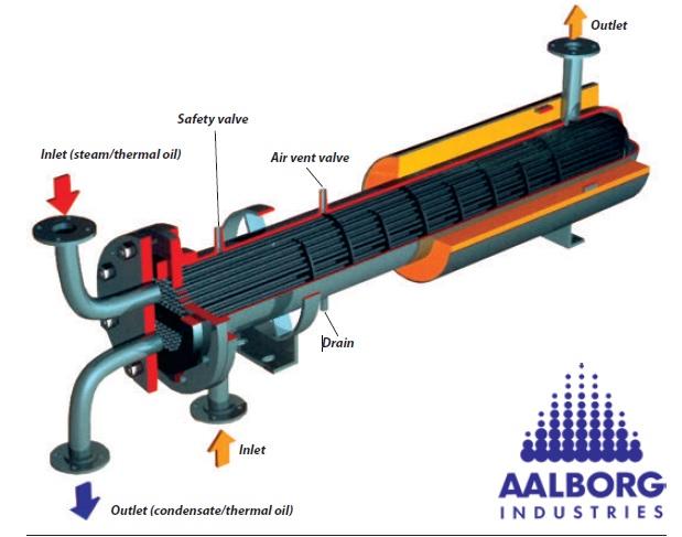
TUBE TYPE HEAT EXCHANGER
Fig: TUBE TYPE HEAT EXCHANGER


Shell and tube coolers

Shell and tube heat exchangers for engine cooling water and lubricating oil cooling have traditionally been circulated with sea water. The sea water is in contact with the inside of the tubes, tube plates and water boxes. A two-pass flow is shown in the diagram but straight flow is common in small coolers. The oil or water being cooled is in contact with the outside of the tubes and the shell of the cooler. Baffles direct the liquid across the tubes as it flows through the cooler. The baffles also support the tubes and form with them a structure which is referred to as the tube stack. The usual method of securing the tubes is to roll-expand them.

Tubes of alluminium brass ( 76% copper , 22% zinc, 2% aluminium ) are commonly employed and the successful use of this material has apparently depended on the presence of a protective film of iron ions, formed along the tube length, by corrosion of iron in the system. Unprotected iron in water boxes and in parts of the pipe system, while itself corroding, does assist in prolonging tube life. This factor is well known (Cotton and Scholes, 1972) but has been made apparent when iron and steel in pipe systems have been replaced by non-ferrous metals or shielded by a protective coating. The remedy in non-ferrous systems, has been to supply iron ions from other sources. Thus, soft iron sacrificial anodes have been fitted in water boxes, iron sections have been inserted in pipe systems and iron has been introduced into the sea water, in the form of ferrous sulphate. The latter treatment consists of dosing the sea water to a strength of 1 ppm for an hour per day for a few weeks and subsequently dosing again before entering and after leaving port for a short period.

Electrical continuity in the sea-water circulating pipework is important where sacrificial anodes are installed. Metal connectors are fitted across flanges and cooler sections where there are rubber joints and 'O' rings, which otherwise insulate the various parts of the system.

Premature tube failure can be the result of pollution in coastal waters or extreme turbulence due to excessive sea-water flow rates. To avoid the impingement attack, care must be taken with the water velocity through tubes. For aluminium-brass, the upper limit is about 2.5 m/s. Although it is advisable to design to a lower velocity than this — to allow for poor flow control - it is equally bad practice to have sea-water speeds of less than 1 /sec. A more than minimum flow is vital to produce moderate turbulence which is essential to the heat exchange process and to reduce silting and settlement in the tubes. Naval brass tube plates are used with aluminium-brass tubes. The tube stacks are made up to have a fixed tube plate at one end and a tube plate at the other end which is free to move when the tubes expand or contract. The tube stack is constructed with baffles of the disc and ring, single or double segmental types. The fixed end tube plate is sandwiched between the shell and water box, with jointing material, Synthetic rubber 'O' rings for the sliding tube plate permit free expansion.

Type of cooler described: This may prolong cooler life by reversing the flow so that tube entrances, which are prone to impingement damage, become outlets. Cooler end covers and water boxes are commonly of cast iron or fabricated from mild steel. Unprotected cast iron in contact with sea water, suffers from graphitization, a form of corrosion in which the iron is removed and only the soft black graphite remains.

The shell is in contact with the liquid being cooled which may be oil, distilled or fresh water with corrosion inhibiting chemicals. It may be of cast iron or fabricated from steel. Manufacturers recommend that coolers be arranged vertically. Where horizontal installation is necessary, the sea water should enter at the bottom and leave at the top. Air in the cooler system will encourage corrosion and air locks will reduce the cooling area and cause overheating. Vent cocks should be fitted for purging air and cocks or a plug are required at the bottom, for draining. Clearance is required at the cooler fixed end for removal of the tube stack,

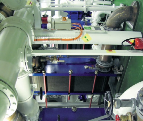
PLATE TYPE HEAT EXCHANGER
Fig: PLATE TYPE HEAT EXCHANGER


Plate type heat exchangers

The obvious feature of plate type heat exchangers, is that they are easily opened for cleaning. The major advantage over tube type coolers, is that their higher efficiency is reflected in a smaller size for the same cooling capacity. They are made up from an assembly of identical metal pressings with horizontal or chevron pattern corrugations; each with a nitrile rubber joint. The plates, which are supported beneath and located at the top by parallel metal bars, are held together against an end plate by clamping bolts. Four branch pipes on the end plates, align with ports in the plates through which two fluids pass. Seals around the ports are so arranged that one fluid flows in alternate passages between plates and the second fluid in the intervening passages, usually in opposite directions.

The plate corrugations promote turbulence in the flow of both fluids and so encourage efficient heat transfer. Turbulence as opposed to smooth flow causes more of the liquid passing between the plates to come into contact with them. It also breaks up the boundary layer of liquid which tends to adhere to the metal and act as a heat barrier when flow is slow. The corrugations make the plates stiff so permitting the use of thin material. They additionally increase plate area. Both of these factors also contribute to heat exchange efficiency.

Excess turbulence, which can result in erosion of the plate material, is avoided by using moderate flow rates. However, the surfaces of plates which are exposed to sea water are liable to corrosion/erosion and suitable materials must be selected. Titanium plates although expensive, have the best resistance to corrosion/erosion. Stainless steel has also been used and other materials such as aluminium-brass. The latter may not be ideal for vessels which operate in and out of ports with polluted waters.

The nitrile rubber seals are bonded to the plates with a suitable adhesive. Removal is facilitated with the use of liquid nitrogen which freezes, makes


Related Information:

Heat exchanger precautions

Advantages of various heat exchangers

Sea water circulation of coolers for lubricating oil, piston cooling, jacket water, charge air, turbo-charger

Marine diesel engine related other useful articles:
  1. Four stroke cycle diesel engines operational guideline

  2. The four-stroke cycle is completed in four strokes of the piston, or two revolutions of the crankshaft. In order to operate this cycle the engine requires a mechanism to open and close the inlet and exhaust valves
    More .....

  3. Two stroke cycle diesel engines operational guideline

  4. The two-stroke cycle is completed in two strokes of the piston or one revolution of the crankshaft. In order to operate this cycle where each event is accomplished in a very short time, the engine requires a number of special arrangements.
    More .....

  5. Power measurement for marine diesel engine - The engine indicator

  6. There are two possible measurements of engine power: the indicated power and the shaft power. The indicated power is the power developed within the engine cylinder and can be measured by an engine indicator. The shaft power is the power available at the output shaft of the engine and can be measured using a torsionmeter or with a brake.
    More .....

  7. Supply of fresh air and removal of exhaust gases by a gas exchanger

  8. A basic part of the cycle of an internal combustion engine is the supply of fresh air and removal of exhaust gases. This is the gas exchange process. Scavenging is the removal of exhaust gases by blowing in fresh air.
    More .....

  9. The fuel oil system for a diesel engine

  10. The fuel oil system for a diesel engine can be considered in two parts—the fuel supply and the fuel injection systems. Fuel supply deals with the provision of fuel oil suitable for use by the injection system.
    More .....

  11. Lubricating oil system for a marine diesel engine - how it works

  12. The lubrication system of an engine provides a supply of lubricating oil to the various moving parts in the engine. Its main function is to enable the formation of a film of oil between the moving parts, which reduces friction and wear. The lubricating oil is also used as a cleaner and in some engines as a coolant.
    More .....

  13. Cooling of ships engine - how it works , requirement of fresh water & sea water cooling system

  14. Cooling of engines is achieved by circulating a cooling liquid around internal passages within the engine. The cooling liquid is thus heated up and is in turn cooled by a sea water circulated cooler. Without adequate cooling certain parts of the engine which are exposed to very high temperatures, as a result of burning fuel, would soon fail.
    More .....

  15. Starting air system for diesel engine - how it works

  16. Diesel engines are started by supplying compressed air into the cylinders in the appropriate sequence for the required direction. A supply of compressed air is stored in air reservoirs or 'bottles' ready for immediate use. Up to 12 starts are possible with the stored quantity of compressed air.
    More .....

  17. Governor-Function of governors controlling speed of marine diesel engine

  18. The principal control device on any engine is the governor. It governs or controls the engine speed at some fixed value while power output changes to meet demand. This is achieved by the governor automatically adjusting the engine fuel pump settings to meet the desired load at the set speed.
    More .....

  19. Cylinder relief valve of a marine diesel engine - operational guideline

  20. The cylinder relief valve is designed to relieve pressures in excess of 10% to 20% above normal. The operation of this device indicates a fault in the engine which should be discovered and corrected.
    More .....

  21. Explosion relief valve of a marine diesel engine

  22. As a practical safeguard against explosions which occur in a crankcase, explosion relief valves or doors are fitted. These valves serve to relieve excessive crankcase pressures and stop flames being emitted from the crankcase. They must also be self closing to stop the return of atmospheric air to the crankcase.
    More .....

  23. Turning gear operational guideline
    The turning gear or turning engine is a reversible electric motor which drives a worm gear which can be connected with the toothed flywheel to turn a large diesel. A slow-speed drive is thus provided to enable positioning of the engine parts for overhaul purposes.
    More .....

  24. Couplings, clutches and gearboxes of a marine diesel engine

  25. The principal control device on any engine is the governor. It governs or controls the engine speed at some fixed value while power output changes to meet demand. This is achieved by the governor automatically adjusting the engine fuel pump settings to meet the desired load at the set speed.
    More .....

  26. MAN B&W diesel engine - Basic principles and operational guideline

  27. It is one of the MC series introduced in 1982, and has a longer stroke and increased maximum pressure when compared with the earlier L-GF and L-GB designs.
    More .....

  28. Crankcase oil mist detector of a marine diesel engine

  29. It is one of the MC series introduced in 1982, and has a longer stroke and increased maximum pressure when compared with the earlier L-GF and L-GB designs.
    More .....

  30. Various Heat exchanger for running machinery on board cargo ships

  31. Shell and tube heat exchangers for engine cooling water and lubricating oil cooling have traditionally been circulated with sea water. The sea water is in contact with the inside of the tubes, tube plates and water boxes.
    More .....

  32. Guideline for Turbochargers safety and operational requirement

  33. Shell and tube heat exchangers for engine cooling water and lubricating oil cooling have traditionally been circulated with sea water. The sea water is in contact with the inside of the tubes, tube plates and water boxes.
    More .....

  34. Function of Piston & piston rings

  35. Piston forms the lower part of the combustion chamber. It seals the cylinder and transmits the gas pressure to the connecting rod. The Piston comprises of two pieces; the crown and the skirt.The crown of a piston is subject to mechanical and thermal stresses.
    More .....


Marine machineries - Useful tags

Marine diesel engines ||Steam generating plant ||Air conditioning system ||Compressed air ||Marine batteries ||Cargo refrigeration ||Centrifugal pump ||Various coolers ||Emergency power supply ||Exhaust gas heat exchangers ||Feed system ||Feed extraction pump || Flow measurement || Four stroke engines || Fuel injector || Fuel oil system || Fuel oil treatment ||Gearboxes || Governor || Marine incinerator || Lub oil filters || MAN B&W engine || Marine condensers || Oily water separator || Overspeed protection devices || Piston & piston rings || Crankshaft deflection || Marine pumps || Various refrigerants || Sewage treatment plant || Propellers || Power Plants || Starting air system || Steam turbines || Steering gear || Sulzer engine || Turbine gearing || Turbochargers || Two stroke engines || UMS operations || Drydocking & major repairs || Critical machinery || Deck machineries & cargo gears || Control and instrumentation ||Fire protection ||Engine room safety ||


Machinery Spaces.com is about working principles, construction and operation of all the machinery items in a ship intended primarily for engineers working on board and those who working ashore . For any remarks please Contact us

Copyright © 2010-2016 Machinery Spaces.com All rights reserved.
Terms and conditions of use
Read our privacy policy|| Home page||