Heavy Fuel Oil Separation Control for Marine Fuel Oil Systems
Changes in refinery techniques are resulting in heavy fuel oils with
increased density and usually contaminated with catalytic fines. These
are small particles of the catalysts used in the refining process. They are
extremely abrasive and must be removed from the fuel before it enters
the engine. The generally accepted maximum density limit for purifier
operation is 991 kg/m3 at 15 deg C.
Fuel oil treatment Fuels supplied to a ship must be treated on board before use in order
to remove solid as well as liquid contaminants. The solid contaminants in the fuel are
mainly rust, sand, dust and refinery catalysts. Liquid contaminants are mainly fresh or salt
water. The settling tank is the first step in fuel treatment process. Water and sediments
can be separated by gravity and drained off at the bottom of the tank. Effective cleaning
of residual fuels can only be ensured by centrifuges: a clarifier to separate particles and/
or a purifier to separate water. In order to remove any solid particles not separated by
centrifuging, fine filters are placed directly after the centrifuge, or in the supply line to
the engine.
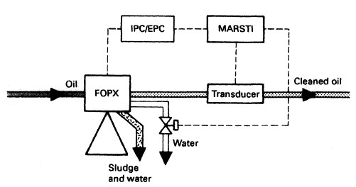
Heavy fuel oil separation system :In the ALCAP separation system the separator has no gravity disc and
operates, to some extent, as a clarifier. Clean oil is discharged from the
oil outlet and separated sludge and water collect at the periphery of the
bowl. When the separated water reaches the disc stack, some water will
escape with the cleaned oil. The increase in water content is sensed by a
water-detecting transducer in the outlet .
The water
transducer signal is fed to the MARST 1 microprocessor which will
discharge the water when a predetermined level is reached. The water
will be discharged from sludge ports in the bowl or, if the amount is
large, from a water drain valve.
The ALCAP system has also proved effective in the removal of
catalytic fines from fuel oil.
Fig : Fuel oil separation control
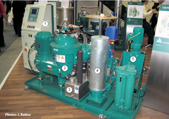
Fig: FUEL OIL TREATMENT PLANT WITH CENTRIFUGAL SEPARATOR
1. Control and monitoring unit
2. Separator
3. Sludge transfer unit
4. Heater unit Image credit : Wärtsilä Encyclopedia of Ship Technology
General Safety and good practice with regard to Fuel Oil Systems and pipelines
This procedure shall ensure that full and proper maintenance is carried out to accepted and safe standards.
Leakage from fuel pressure systems are a serious fire hazard. The PMS is required to include the following checks:
Fuel pump restraining bolts must be proven tight by testing with a torque spanner at frequent intervals. Please include such a test in your PM system with an interval of 3 months.
The supports and retaining devices of the low pressure fuel system must be checked at regular intervals and be proved tight and providing adequate restraint. The lining of such devices must also be examined for wear and renewed if they provide insufficient support. Please include such a test in your PM system with an interval of 3 months.
Flexible pipes must be closely examined and renewed if signs of material cracking or deterioration are evident. Extra care must be exercised in the tightening of these pipe connections to ensure that they are not twisted when re-installed.
All gasket and seal ring materials, and any jointing compounds used must comply with the requirements of the engine manufacturer.
Compression fittings are to be carefully examined and tightened (but not over-tightened), in accordance with the manufacturer’s specification. Copper piping must be heat treated (annealed) and sufficient supports fitted to prevent vibration
All component locking devices, such as spring and tab washers, locking wires, etc. must be present and currently fitted.
Spray or deflection plates and insulation must be correctly replaced after maintenance to reduce the possibility of fire in the event of fuel leakage.
The installed system is to be inspected at regular intervals for the level of vibration present and evidence of fatigue stresses to welded or brazed pipes and connections.
De-Sludging & Cleaning of Fuel Tanks
It is essential that all fuel tanks are regularly "de-sludged" using the sludge cocks provided. They must never be operated by artificial means. The presence of water in appreciable quantities must be immediately brought to the attention of the Chief Engineer.
This is to be carried out at four hourly intervals on a conventional watchkeeping vessel. Prior entering a bad weather area and whilst in heavy weather conditions, the frequency of draining must be increased.
On vessels operating for periods of time with unmanned engine room spaces, the interval between sludging during the manned period is to be four hours.
For the unmanned period, this is to be detailed by the Chief Engineer in the Night Order Book, however it is to be not less than three times during that period i.e. at commencement of the unmanned period, during the late evening inspection of the Engine Room spaces, and at the end of the unmanned period. All other double bottom and/or deep bunker tanks are subject to Classification inspection and would normally only be inspected on a 60 month frequency.
Each Service and Settling fuel tanks, on a rotational basis, are to be emptied at intervals not exceeding 36 months or at Dry Dock. This is for the purpose of sighting the internal condition, in particular any build up of sludge, solids and other contaminants. Manual cleaning is to be done if applicable, during a safe period at a safe location, with suitable notice to the Master. Testing of all float alarms where applicable should be done at this time.
It is strictly forbidden to enter a fuel tank unless the appropriate "enclosed space entry permit" conditions have been complied with and the permit issued.
Known contamination with solids such as "Catalytic Fines" can only be dealt with by taking the tank out of service, isolation, and subsequent manual cleaning.
The opportunity must be taken when tanks are cleaned to test any heating coils fitted, and check/overhaul all the tank mountings including examination of vent pipes for obstruction etc.
Heating of sludge oil tanks, waste oil and oily water bilge tanks in order to extract water
Care must be taken when using internal heating coils. The heating of a water/oil mix from any such oil or sludge tank must be deemed as a critical operation .
While preparing the checklist, it should be kept in mind that any heating of the sludge/oil water mix will expand the volume of the liquid and may cause an overflow of the tanks. A maximum filling level for such tanks must be identified that leaves a safety margin for this expansion. This level should be recorded on the checklist.
Operations must be recorded in the ORB
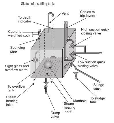
Sketch of a fuel oil settling tank
Use of Settling tank
A deep tank in the engine room used for pre-cleaning of fuel oils by gravity;
a liquid mixture in the settling tank clears slowly as a heavier liquid and solids sink to the
bottom under influence of gravity.
Usually there are two settling tanks, each with a capacity sufficient for 24 hours full load
operation of all consumers. Tanks should be designed to provide the most efficient
sludge and water separation.
Each settling tank should be provided with baffles to
reduce mixing of sludge with the fuel. The bottom of the tank should be with slope
toward the sludge drains, and pump suction shall be not in the vicinity of the sludge
space. The temerature in fuel settling tanks should be as high as possible to help the
dirt to settle. However, the temperature should be below 75°C in order to avoid the
formation of asphaltenes, and min 7°C above the pour point of the fuel to ensure
pumpability.
Settling tanks use gravitation for the purification of fuel oil.
When the oil is allowed to stand undisturbed in the tank,
particles and liquids of higher density than oil will gravitate
to the bottom of the tank where they are discharged every
so often by a manually operated spring-loaded sludge cock.
This process can be speeded up by applying heat to the tank's
contents.
Steam heating coils are provided for this purpose, but
care must be taken that the oil is not heated to too high a
temperature. These tanks are normally lagged to keep the heat
in.
The function of the dumping valve fitted to a fuel oil settling
tank is to dump the oil from an elevated settling tank to a lower
bunker double bottom tank in the event of a fire in the engine
room or close to the tank. The function of the sludge valve or sludge cock fitted to a
settling tank is to drain water or sludge at the bottom of the
tank to any oily bilge or sludge tank.
The cocks are of a self-closing type.
Machinery Spaces.com is about working principles, construction and operation of all the machinery
items in a ship intended primarily for engineers working on board and those who working ashore . For any remarks please
Contact us