Machinery Spaces
Home || Diesel Engines ||Boilers||Feed Systems ||Steam Turbines ||Fuel Treatment ||Pumps ||Refrigeration ||

Fuel oil centrifuging for marine use

Treatment of fuel oils and lubricating oils : Both fuel oils and lubricating oils require treatment before passing to the engine. This will involve storage and heating to allow separation of water present, coarse and fine filtering to remove solid particles and also centrifuging.

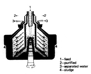
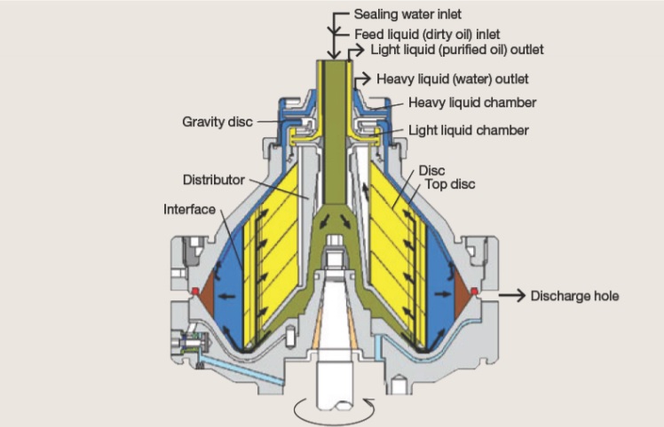
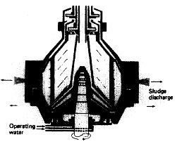
The centrifugal separator is used to separate two liquids, for example oil and water, or a liquid and solids as in contaminated oil. Separation is speeded up by the use of a centrifuge and can be arranged as a continuous process. Where a centrifuge is arranged to separate two liquids, it is known as a 'purifier'. Where a centrifuge is arranged to separate impurities and small amounts of water from oil it is known as a 'clarifier'.

ships machinery spaces
container ships machinery info
The separation of impurities and water from fuel oil is essential for good combustion. The removal of contaminating impurities from lubricating oil will reduce engine wear and possible breakdowns. The centrifuging of all but the most pure clean oils is therefore an absolute necessity.

Centrifuging

A centrifuge consists of an electric motor drive to a vertical shaft on the top of which is mounted the bowl assembly. An outer framework surrounds the assembly and carries the various feed and discharge connections. The bowl can be a solid assembly which retains the separated sludge and operates non-continuously, or the bowl can be arranged so that the upper and lower parts separate and the sludge can be discharged while the centrifuge operates continuously. The dirty oil is admitted into the centre of the bowl, passes up through a stack of discs and out through the top.


Purifying bowl arrangement

Fig: Purifying bowl arrangement


The purifying process

The centrifugal separation of two liquids, such as oil and water, results in the formation of a cylindrical interface between the two. The positioning of this interface within the centrifuge is very important for correct operation. The setting or positioning of the interface is achieved by the use of dam rings or gravity discs at the oudet of the centriiuge. Various diameter rings are available for each machine when different densities of oil are used. As a general rule, the largest diameter ring which does not break the 'seal' should be used.

cross section through HFO purifier

Fig: Cross section through HFO purifier

The clarifying process

Cleaning oil which contains little or no water is achieved in a clarifier bowl where the impurities and water collect at the bowl periphery. A clarifier bowl has only one outlet . No gravity disc is necessary since no interface is formed; the bowl therefore operates at maximum separating efficiency since the oil is subjected to the maximum centrifugal force,


The bowl discs

Purifier and clarifier bowls each contain a stack of conical discs. The discs may number up to 150 and are separated from one another by a small gap. Separation of impurities and water from the oil takes place between these discs. A series of aligned holes near the outside edge permits entry of the dirty oil. The action of centrifugal force causes the lighter components (the clean oil) to flow inwards and the water and impurities flow outwards. The water and impurities form a sludge which moves outwards along the undersides of the discs to the periphery of the bowl.


Non-continuous operation

Certain designs of centrifuges are arranged for a short period of operation and are then shut down for cleaning. After cleaning and removal of the sludge from the bowl, the machine is returned to service. Two different designs are used for this method of operation; a long narrow bowl and a short wide bowl.

The narrow-bowl machine has to be cleaned after a shorter running period and requires dismantling in order to clean the bowl. Cleaning of the bowl is, however, much simpler since it does not contain a stack of discs. The wide-bowl machine can be cleaned in place, although there is the added complication of the stack of conical discs which must be cleaned.

Sludge discharge

Fig: Sludge discharge arrangement


Continuous operation - sludge discharge

Modern wide-bowl centrifuge designs enable continuous operation over a considerable period of time. This is achieved by an ejection process which is timed to discharge the sludge at regular intervals. The sludge deposits build up on the bowl periphery as separation continues, and the ejection process is timed to clear these deposits before they begin, to affect the separation process.

To commence the ejection process the oil feed to the centrifuge is first shut off and the oil remaining in the bowl is removed by admitting flushing water. Water is then fed into the hydraulic system in the bottom of the bowl to open a number of spring-loaded valves. This 'operating' water causes the sliding bowl bottom to move downwards and open discharge ports in the bowl periphery. The sludge is discharged through these ports by centrifugal force. Closing 'operating' water is now fed in to raise the sliding bowl up again and close the discharge ports. Water is fed into the bowl to remake the liquid seal required for the separation process, the oil feed reopened, and separation continues.

The complete ejection cycle takes only a few seconds and the centrifuge is in continuous operation throughout. Different bowl designs exist for various forms of sludge discharge, e.g. total discharge, controlled partial discharge, and so on. With controlled partial discharge the oil supply is not shut off and not all of the sludge is discharged. In this way the separation process is not stopped. Whatever method is adopted the centrifuge can be arranged so that the discharge process is performed manually or by an automatic timer.


Maintenance

The bowl and the disc stack will require periodical cleaning whether or not an ejection process is in operation. Care should be taken in stripping down the bowl, using only the special tools provided and noting that some left-hand threads are used. The centrifuge is a perfectly balanced piece of equipment, rotating at high speeds: all parts should therefore be handled and treated with care.


Related Info:

Fuel oils treatment for marine use -The refining process for crude oil

Fuel oil separation process

Marine fuel oil treatment - use of filters and strainers

Lubricating oils treatment for marine use

Marine fuel oil Microbiological infestation

Fuel oil blenders

Lubricating oil centrifuging for marine use

Function of oil in water monitor


Marine machineries - Useful tags

Marine diesel engines ||Steam generating plant ||Air conditioning system ||Compressed air ||Marine batteries ||Cargo refrigeration ||Centrifugal pump ||Various coolers ||Emergency power supply ||Exhaust gas heat exchangers ||Feed system ||Feed extraction pump || Flow measurement || Four stroke engines || Fuel injector || Fuel oil system || Fuel oil treatment ||Gearboxes || Governor || Marine incinerator || Lub oil filters || MAN B&W engine || Marine condensers || Oily water separator || Overspeed protection devices || Piston & piston rings || Crankshaft deflection || Marine pumps || Various refrigerants || Sewage treatment plant || Propellers || Power Plants || Starting air system || Steam turbines || Steering gear || Sulzer engine || Turbine gearing || Turbochargers || Two stroke engines || UMS operations || Drydocking & major repairs || Critical machinery || Deck machineries & cargo gears || Control and instrumentation ||Fire protection ||Engine room safety ||


Machinery Spaces.com is about working principles, construction and operation of all the machinery items in a ship intended primarily for engineers working on board and those who working ashore . For any remarks please Contact us

Copyright © 2010-2016 Machinery Spaces.com All rights reserved.
Terms and conditions of use
Read our privacy policy|| Home page||