Machinery Spaces
Home || Diesel Engines ||Boilers||Feed Systems ||Steam Turbines ||Fuel Treatment ||Pumps ||Refrigeration ||

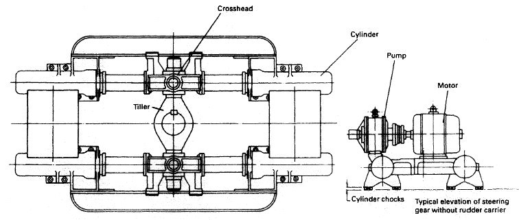
Ships Steering Gear Arrangement & Testing

Steering Gear – is used for of steering the ship. It is in constant use when the ship is underway, and any failure or malfunction may result in disaster. The steering system usually consists of: a steering gear, a control equipment, a rudder carrier, a rudder and a rudder horn. The steering gear provides a movement of the rudder in response to a signal from the bridge. The control equipment conveys a signal of ordered rudder angle from the bridge and activates the steering gear to move the rudder to the desired angle.

ships machinery spaces
container ships machinery info
The three basic requirements of steering gear are :
  1. To be continuously available, move the rudder rapidly to any position of degrees in response to the order from the bridge during manoeuvring and hold it in the required position
  2. have arrangements for relieving abnormal stress and returning it to its required position
  3. maintain the ship on course regardless of wind and waves.

Testing in Port and prior to Departure
The regulations SOLAS Chapter V Regulation 26 and 33 CFR Chapter 1 164.25 “Tests before entering or getting underway” have to be complied with. During stays in port between voyages or passages a test is to be carried out within 12 hours of the estimated time of "stand by departure".

Normal acceptable practice is one hour before departure, with all the generator/alternator engines required for standby on line, and Bridge and Engine room watchkeeping officers on duty. Prior to testing, the following checks are to be carried out :
Testing is to include the following:
  1. The main steering gear, power units, pumps, and hydraulic machinery.
  2. All the bridge manual steering controls.


  3. The bridge/steering spaces electric control system.
  4. Manual operation of steering control.
  5. Power Unit failure alarms.
  6. All remote rudder angle indicators.
  7. Swinging the rudder from hard to port to hard to starboard.
  8. Automatic isolating arrangements and other automatic equipment.

During this operation, the remote rudder angle indicators are to be checked for accuracy with the master indicator affixed to the steering gear. The ammeter readings from both motors are to be recorded in the Engine Room Log. The time taken for the rudder to move from hard over (35 degrees) from one side to the other is to be recorded for both motors singly and then both together. These times are to be compared with the manufacturer’s specified times.

4 ram steering gear

Fig:Typical 4 ram steering gear arrangement for cargo ships


If the time taken to move the rudder from 35 degrees on either side to 30 degrees on the other side exceeds 28 seconds when using both motors, then the appropriate management office is to be advised. It is important that as the rudder approaches the hard over position, the “stroke” comes off the pump or pumps in use, slowing down the rate of discharge from the pumps and thus the rate of traverse of the rudder. This functionality is necessary in order that the rudder does not overshoot the designed limits of travel. A feedback arrangement consisting of a floating link in the control of the pumps or an equivalent electronic arrangement takes care of this and it is important that testing of the steering system checks that this happens.

When hard-over, the rudder must not exceed its designated limit as this could lead to the rudder getting stuck in this position. The SOLAS requirement is 35 degrees on both sides.

A creep test is to be carried out, and the results recorded in the Engine Room Log. Proof marks of rudder to tiller arm, and vessels with taper fit connections are to be checked to ensure no displacement or slippage has taken place. Wear down is to be checked using the poker gauge or other device as appropriate, and the readings recorded in the Engine Room Log.

Where no proof marks or means of checking are available the office is to be informed, and such marks introduced as soon as possible. In port, when the vessel is at a suitable draft and access is available, the Chief Engineer is to sight the rudder stock connections i.e. palm bolts etc. and where possible the jumping clearance. With rudders which do not have externally visible connections, the position of the rudder in a horizontal plane relative to the sternframe/hull is to be carefully scrutinised.

Any evidence of damage, slackness, or alteration in the rudder position relative to the vessel's hull in a horizontal plane is to be reported to the Office immediately. Following a repair period, drydocking, or lay up, a test is to be carried out as soon as is practical.


Testing at Sea

Testing of the steering gear at sea is at the jurisdiction of the Master. The Master is to be on the Bridge and the Chief Engineer in the steering gear compartment at the time of the test. (33CFR Chapter 1 164.25 to be complied with)

Under normal sea speed, the rudder is to be put from hard to port to hard to starboard on one motor, and then on the other motor. This process is then to be repeated using both motors. The ammeter readings during these tests are to be recorded and entered in the Engine Room Log Book. If the time taken to move the rudder from 35 degree on either side to 30 degree on the other side exceeds 28 seconds when using both motors then the appropriate management office is to be advised.

On vessels with steering gear designed to operate with only one motor on even when manoeuvring (the second motor being on stand-by), single motor operation should meet this criteria. A creep test is also to be carried out and the results recorded in the Engine Room Log Book. Creep Test - With 1 motor on a setting midships If the rudder creeps more than 5 degrees in one minute then management office is to be advised.


Emergency Steering Drill

An Emergency Steering Drill is to be carried out at least once every 3 months. It is to consist of direct operation of the main steering gear by manual control within the steering compartment. Steering is to be directed by communication from the bridge to the steering compartment. Where applicable, the operation of alternative power supplies is to be tested. Notices are to be posted next to the steering gear emergency station with a warning that no testing of the steering gear control system or its components is to take place whilst the vessel is underway, unless under the direct supervision of the Chief Engineer. All ship’s staff must be made aware of this requirement.


Electrical, Hydraulic and Mechanical Change-Over Procedures

All Engineer Officers must be able to carry out the electrical, hydraulic and mechanical change-over procedures. If not in existence, a valve position diagram must be produced with the position of all valves. Such valves are to be clearly marked by numbers or letters.

These diagrams would normally show the following situations, unless the steering gear is of the rotary vane type:

a) Starboard hydraulic pump in use;
b) Port hydraulic pump in use;
c) Starboard and port hydraulic pump in use;
d) Emergency hydraulic pump in use;
e) All four hydraulic rams in use;
f) Only after opposite hydraulic ram in use;
g) Only forward opposite hydraulic ram in use;
h) Only starboard hydraulic rams in use;
i) Only port hydraulic rams in use.

The Master and Chief Engineer are to report to the relevant Management Office, common hydraulic pipes in the system which in case of failure, would result in having the whole steering gear out of order.


Rudder Arrestor Systems

On vessels fitted with a rudder arrestor system, all Engineer Officers must be familiar with, and be able to operate, the system.


Records

Log Book entries are to be made when all inspections and tests are conducted and when emergency steering drills are carried out.


Related information

  1. Ships steering gear testing requirement
  2. The regulations SOLAS Chapter V Regulation 26 and 33 CFR Chapter 1 164.25 “Tests before entering or getting underway” have to be complied with. During stays in port between voyages or passages a test is to be carried out within 12 hours of the estimated time of "stand by departure"....

  3. Oil lubricated sterntube bearing, sterntube seals & shafting arrangement
  4. The sterntube bearing serves two important purposes. It supports the tailshaft and a considerable proportion of the propeller weight. It also acts as a gland to prevent the entry of sea water to the machinery space.....

  5. Function of solid fixed pitch propeller & Propeller mounting
  6. The propeller consists of a boss with several blades of helicoidal form attached to it. When rotated it 'screws' or thrusts its way through the water by giving momentum to the column of water passing through it. The thrust is transmitted along the shafting to the thrust block and finally to the ship's structure....

  7. Controllable pitch propeller
  8. A controllable pitch propeller is made up of a boss with separate blades mounted into it. An internal mechanism enables the blades to be moved simultaneously through an arc to change the pitch angle and therefore the pitch....

  9. Ships propeller shaft -Thrust block & Shaft bearings
  10. The transmission system on a ship transmits power from the engine to the propeller. It is made up of shafts, bearings, and Finally the propeller itself. The thrust from the propeller is transferred to the ship through the transmission system....

  11. Ships steering gear arrangement and testing requirement
  12. The main steering gear is to be capable of putting the rudder over from 35° on one side to 35° on the other side with the ship at its deepest draft and running ahead at maximum service speed, and under the same conditions from 35° on either side to 30° on the other side in not more than 28 seconds.....

  13. Ships steering gear electrical control
  14. The electrical remote control system is commonly used in modern installations since it uses a small control unit as transmitter on the bridge and is simple and reliable in operation.Movement of the bridge transmitter results in electrical imbalance and current flow to the motor. .....

  15. Ships steering gear telemotor control
  16. Telemotor control is a hydraulic control system employing a transmitter, a receiver, pipes and a charging unit. The transmitter, which is built into the steering wheel console, is located on the bridge and the receiver is mounted on the steering gear..

    .....
  17. Ships steering gear testing requirement
  18. The regulations SOLAS Chapter V Regulation 26 and 33 CFR Chapter 1 164.25 “Tests before entering or getting underway” have to be complied with. During stays in port between voyages or passages a test is to be carried out within 12 hours of the estimated time of "stand by departure"....


Marine machineries - Useful tags

Marine diesel engines ||Steam generating plant ||Air conditioning system ||Compressed air ||Marine batteries ||Cargo refrigeration ||Centrifugal pump ||Various coolers ||Emergency power supply ||Exhaust gas heat exchangers ||Feed system ||Feed extraction pump || Flow measurement || Four stroke engines || Fuel injector || Fuel oil system || Fuel oil treatment ||Gearboxes || Governor || Marine incinerator || Lub oil filters || MAN B&W engine || Marine condensers || Oily water separator || Overspeed protection devices || Piston & piston rings || Crankshaft deflection || Marine pumps || Various refrigerants || Sewage treatment plant || Propellers || Power Plants || Starting air system || Steam turbines || Steering gear || Sulzer engine || Turbine gearing || Turbochargers || Two stroke engines || UMS operations || Drydocking & major repairs || Critical machinery || Deck machineries & cargo gears || Control and instrumentation ||Fire protection ||Engine room safety ||


Machinery Spaces.com is about working principles, construction and operation of all the machinery items in a ship intended primarily for engineers working on board and those who working ashore . For any remarks please Contact us

Copyright © 2010-2016 Machinery Spaces.com All rights reserved.
Terms and conditions of use
Read our privacy policy|| Home page||