Machinery Spaces
Home || Diesel Engines ||Boilers||Feed Systems ||Steam Turbines ||Fuel Treatment ||Pumps ||Refrigeration ||

Oil lubricated sterntube bearing, sterntube seals & shafting arrangement

Sterntube is the watertight tube enclosing and supporting the propeller shaft. It consists of a cast-iron or casted steel cylinder fitted with bearing surface within which the propeller shaft, enclosed in a sleeve, rotates. The sterntube is installed from aft and bolted to the stern frame boss. It can be press-fitted or installed with epoxy resin.

Sterntube bearings – Oil-lubricated white metal bearing usually consists of two bushes pressed into a stern-tube. Water lubricated bearings use only seawater for lubrication, thereby they eliminate any risk of oil pollution from the sterntube.
ships machinery spaces
container ships machinery info
The sterntube bearing serves two important purposes. It supports the tailshaft and a considerable proportion of the propeller weight. It also acts as a gland to prevent the entry of sea water to the machinery space.

Sterntube lubricating oil systems

In principle, the sterntube aft seals can function without a lubrication system. However, the aft sealing functions better and has a longer life if it is fitted, like the forward sealing, with a lubrication system. Although dated, permanent oil lubrication without circulation is still used. Oil loss can occur if there is no counter pressure from the outboard water. The system with the circulation is safer.

The aft sealing is connected by means of two oil lubrication lines to a settling tank. The oil is circulated by a small oil pump. Any seawater that has leaked through the damaged or worn water seals into oil system can be separated out in the settling tank. Similarly, any oil that has escaped from the oil seals can be drained to the waste oil tanks. Low and high level switches on the settling tank allow clear observation and monitoring of the functioning of the aft seals.

Early arrangements used bearing materials such as lignum vitae (a very dense form of timber) which were lubricated by sea water. Most modern designs use an oil lubrication arrangement for a white metal lined sterntube bearing. One arrangement is shown in Figure below

Oil is pumped to the bush through external axial grooves and passes through holes on each side into internal axial passages. The oil leaves from the ends of the bush and circulates back to the pump and the cooler. One of two header tanks will provide a back pressure in the system and a period of oil supply in the event of pump failure. A low-level alarm will be fitted to each header tank.

Oil pressure in the lubrication system is higher than the static sea water head to ensure that sea water cannot enter the sterntube in the event of seal failure.
Oil lubricated sterntube bearing
Fig: Oil lubricated sterntube bearing


Sterntube seals

Sterntube seals, propeller shaft seals – A housing with series of seal rings clamped into position on the bush. Sterntube seals have to perform two separate functions, one is to ensure that water does not enter the engine room, the second one to allow the propeller shaft to rotate as smoothly and freely as possible. Oil lubricated sterntube requires two types of seals, one water/oil seal for the external arrangement (aft seal) and one oil seal for the inboard end (forward seal). Modern sterntube seals are highly-engineered units designed and manufactured to withstand a rigorous working environment for long periods. Special seals are fitted at the outboard and inboard ends of the tailshaft. They are arranged to prevent the entry of sea water and also the loss of lubricating oil from the stern bearing.

Older designs, usually associated with sea water lubricated stern bearings, made use of a conventional stuffing box and gland at the after bulkhead. Oil-lubricated stern bearings use either lip or radial face seals or a combination of the two.

Lip seals are shaped rings of material with a projecting lip or edge which is held in contact with a shaft to prevent oil leakage or water entry. A number of lip seals are usually fitted depending upon the particular application.

Face seals use a pair of mating radial faces to seal against leakage. One face is stationary and the other rotates. The rotating face of the after seal is usually secured to the propeller boss. The stationary face of the forward or inboard seal is the after bulkhead. A spring arrangement forces the stationary and rotating faces together.

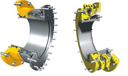
sterntube seals
Fig : sterntube seals

Fig: CoastGuard MC sterntube seal designed to ensure a long service life in cases with high axial shaft movement
Courtesy : https://www.wartsila.com

Sterntube after seal; spacer ring – A split ring mounted on the sterntube. Removal of this ring enables the housing to be moved with respect to the bush, with the result that the lip seals move to an unworn contact surface. This arrangement ensures the optimum use of the bush and significantly extends the life of the entire seal.

The function of the aft sterntube seal is to prevent leakage of lubricating oil from the sterntube outboard, and to prevent seawater from entering the sterntube and contaminating the lubrication system.

The bush of the after seal is made from a high quality chrome steel resistant to corrosion and wear. In order to extend normal life, an optional ceramic coating can be applied. Viton seal rings are then mandatory. The housing is made from seawater resistant bronze. The lip seals are housed in accurately machined rings and are statically sealed by means of a clamping ring.
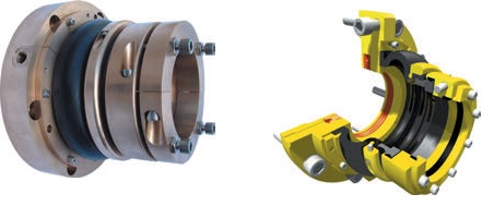
split sterntube seals
Split sterntube seals

Fig: ManeGuard fully split sterntube seal for propulsion shafts of diameters ranging from 100mm to 320mm
Courtesy : https://www.wartsila.com

Split sterntube seals – Split sterntube seals allow the renewal of both lip seal and bush in situ. Split after seals are mostly fitted in cases where the classification society has approved a long interval (10-15 years) between inspections. The split after seal permits inspection of the propeller shaft, particularly the area between the shaft and the flange in installations with CP propellers.


Shafting

There may be one or more sections of intermediate shafting between the thrust shaft and the tailshaft, depending upon the machinery space location. All shafting is manufactured from solid forged ingot steel with integral flanged couplings. The shafting sections are joined by solid forged steel fitted bolts.

The intermediate shafting has flanges at each end and may be increased in diameter where it is supported by bearings. The propeller shaft or tailshaft has a flanged face where it joins the intermediate shafting. The other end is tapered to suit a similar taper on the propeller boss. The tapered end will also be threaded to take a nut which holds the propeller in place.


Related information

  1. Oil lubricated sterntube bearing, sterntube seals & shafting arrangement
  2. The sterntube bearing serves two important purposes. It supports the tailshaft and a considerable proportion of the propeller weight. It also acts as a gland to prevent the entry of sea water to the machinery space.....

  3. Function of solid fixed pitch propeller & Propeller mounting
  4. The propeller consists of a boss with several blades of helicoidal form attached to it. When rotated it 'screws' or thrusts its way through the water by giving momentum to the column of water passing through it. The thrust is transmitted along the shafting to the thrust block and finally to the ship's structure....

  5. Controllable pitch propeller
  6. A controllable pitch propeller is made up of a boss with separate blades mounted into it. An internal mechanism enables the blades to be moved simultaneously through an arc to change the pitch angle and therefore the pitch....

  7. Ships propeller shaft -Thrust block & Shaft bearings
  8. The transmission system on a ship transmits power from the engine to the propeller. It is made up of shafts, bearings, and Finally the propeller itself. The thrust from the propeller is transferred to the ship through the transmission system....


Marine machineries - Useful tags

Marine diesel engines ||Steam generating plant ||Air conditioning system ||Compressed air ||Marine batteries ||Cargo refrigeration ||Centrifugal pump ||Various coolers ||Emergency power supply ||Exhaust gas heat exchangers ||Feed system ||Feed extraction pump || Flow measurement || Four stroke engines || Fuel injector || Fuel oil system || Fuel oil treatment ||Gearboxes || Governor || Marine incinerator || Lub oil filters || MAN B&W engine || Marine condensers || Oily water separator || Overspeed protection devices || Piston & piston rings || Crankshaft deflection || Marine pumps || Various refrigerants || Sewage treatment plant || Propellers || Power Plants || Starting air system || Steam turbines || Steering gear || Sulzer engine || Turbine gearing || Turbochargers || Two stroke engines || UMS operations || Drydocking & major repairs || Critical machinery || Deck machineries & cargo gears || Control and instrumentation ||Fire protection ||Engine room safety ||


Machinery Spaces.com is about working principles, construction and operation of all the machinery items in a ship intended primarily for engineers working on board and those who working ashore . For any remarks please Contact us

Copyright © 2010-2016 Machinery Spaces.com All rights reserved.
Terms and conditions of use
Read our privacy policy|| Home page||