Machinery Spaces
Home || Diesel Engines ||Boilers||Feed Systems ||Steam Turbines ||Fuel Treatment ||Pumps ||Refrigeration ||

Telemotor Control for Ships Steering Gear

The steering gear provides a movement of the rudder in response to a signal from the bridge. The total system may be considered made up of three parts, control equipment, a power unit and a transmission to the rudder stock. The control equipment conveys a signal of desired rudder angle from the bridge and activates the power unit and transmission system until the desired angle is reached.

The power unit provides the force, when required and with immediate effect, to move the rudder to the desired angle. The transmission system, the steering gear, is the means by which the movement of the rudder is accomplished.
ships machinery spaces
container ships machinery info
Telemotor control
Telemotor control is a hydraulic control system employing a transmitter, a receiver, pipes and a charging unit. The transmitter, which is built into the steering wheel console, is located on the bridge and the receiver is mounted on the steering gear. The charging unit is located near to the receiver and the system is charged with a non-freezing fluid.

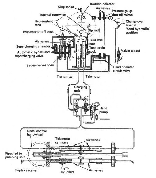
The telemotor system is shown in Figure below. Two rams are present in the transmitter which move in opposite directions as the steering wheel is turned. The fluid is therefore pumped down one pipe line and drawn in from the other. The pumped fluid passes through piping to the receiver and forces the telemotor cylinder unit to move. The suction of fluid from the opposite cylinder enables this movement to take place.

The cylinder unit has a control spindle connected to it by a pin. This control spindle operates the slipper ring or swash plate of the variable delivery pump. If the changeover pin is removed from the cylinder unit and inserted in the local handwheel drive then manual control of the steering gear is possible. Stops are fitted on the receiver to limit movement to the maximum rudder angle required. The charging unit consists of a tank, a pump, and shut-off cocks for each and is fitted in the main piping between the transmitter and receiver.

In the transmitter a replenishing tank surrounds the rams, ensuring that air cannot enter the system. A bypass between the two cylinders opens as the wheel passes midships. Also at mid position the supercharging unit provides a pressure in the system which ensures rapid response of the system to a movement of the wheel. This supercharging unit also draws in replenishing fluid if required in the system, and provides a relief valve arrangement if the pressure is too high. Pressure gauges are connected to each main pipeline and air vent cocks are also provided.

In normal operation the working pressure of about 20 to 30 bar, or the manufacturer's given figure, should not be exceeded. The wheel should not be forced beyond the 'hard over' position as this will strain the gear.

The replenishing tank should be checked regularly and any lubrication points should receive attention. Any leaking or damaged equipment must be repaired or replaced as soon as possible. The system should be regularly checked for pressure tightness. The rudder response to wheel movement should be checked and if sluggish or slow then air venting undertaken. If, after long service, air venting does not remove sluggishness, it may be necessary to recharge the system with new fluid.

Steering gear telemotor control

Fig:Typical Steering gear telemotor control


Automatic pilot, autopilot – Automatic control system used for automatic navigation. The system can sense the difference between the ordered course of the ship and the actual course and will cause the rudder to move to an angle proportional to this error. The autopilot keeps the vessel on the correct heading without the helmsman’s intervention.


Related information

  1. Ships steering gear testing requirement
  2. The regulations SOLAS Chapter V Regulation 26 and 33 CFR Chapter 1 164.25 “Tests before entering or getting underway” have to be complied with. During stays in port between voyages or passages a test is to be carried out within 12 hours of the estimated time of "stand by departure"....

  3. Oil lubricated sterntube bearing, sterntube seals & shafting arrangement
  4. The sterntube bearing serves two important purposes. It supports the tailshaft and a considerable proportion of the propeller weight. It also acts as a gland to prevent the entry of sea water to the machinery space.....

  5. Function of solid fixed pitch propeller & Propeller mounting
  6. The propeller consists of a boss with several blades of helicoidal form attached to it. When rotated it 'screws' or thrusts its way through the water by giving momentum to the column of water passing through it. The thrust is transmitted along the shafting to the thrust block and finally to the ship's structure....

  7. Controllable pitch propeller
  8. A controllable pitch propeller is made up of a boss with separate blades mounted into it. An internal mechanism enables the blades to be moved simultaneously through an arc to change the pitch angle and therefore the pitch....

  9. Ships propeller shaft -Thrust block & Shaft bearings
  10. The transmission system on a ship transmits power from the engine to the propeller. It is made up of shafts, bearings, and Finally the propeller itself. The thrust from the propeller is transferred to the ship through the transmission system....

  11. Ships steering gear arrangement and testing requirement
  12. The main steering gear is to be capable of putting the rudder over from 35° on one side to 35° on the other side with the ship at its deepest draft and running ahead at maximum service speed, and under the same conditions from 35° on either side to 30° on the other side in not more than 28 seconds.....

  13. Ships steering gear electrical control
  14. The electrical remote control system is commonly used in modern installations since it uses a small control unit as transmitter on the bridge and is simple and reliable in operation.Movement of the bridge transmitter results in electrical imbalance and current flow to the motor. .....

  15. Ships steering gear telemotor control
  16. Telemotor control is a hydraulic control system employing a transmitter, a receiver, pipes and a charging unit. The transmitter, which is built into the steering wheel console, is located on the bridge and the receiver is mounted on the steering gear.. .....


Marine machineries - Useful tags

Marine diesel engines ||Steam generating plant ||Air conditioning system ||Compressed air ||Marine batteries ||Cargo refrigeration ||Centrifugal pump ||Various coolers ||Emergency power supply ||Exhaust gas heat exchangers ||Feed system ||Feed extraction pump || Flow measurement || Four stroke engines || Fuel injector || Fuel oil system || Fuel oil treatment ||Gearboxes || Governor || Marine incinerator || Lub oil filters || MAN B&W engine || Marine condensers || Oily water separator || Overspeed protection devices || Piston & piston rings || Crankshaft deflection || Marine pumps || Various refrigerants || Sewage treatment plant || Propellers || Power Plants || Starting air system || Steam turbines || Steering gear || Sulzer engine || Turbine gearing || Turbochargers || Two stroke engines || UMS operations || Drydocking & major repairs || Critical machinery || Deck machineries & cargo gears || Control and instrumentation ||Fire protection ||Engine room safety ||


Machinery Spaces.com is about working principles, construction and operation of all the machinery items in a ship intended primarily for engineers working on board and those who working ashore . For any remarks please Contact us

Copyright © 2010-2016 Machinery Spaces.com All rights reserved.
Terms and conditions of use
Read our privacy policy|| Home page||