Machinery Spaces
Home || Diesel Engines ||Boilers||Feed Systems ||Steam Turbines ||Fuel Treatment ||Pumps ||Refrigeration ||

Anchor Handling Equipment for Cargo Ships

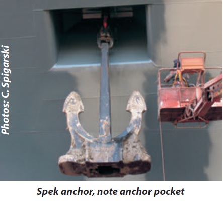
Anchors are heavy forging or casting shaped to grip the sea bottom, and by means of a cable or rope, holds a ship or other floating structure in a desired position regardless of wind and current. Different types are in use: stock-anchors, stockless anchors (SPEK or HALL type), High Holding Power (HHP) anchors, Super Holding Power (SHHP) anchors.

Anchoring equipment is designed for temporary mooring a vessel within a harbour or sheltered area when the vessel is awaiting berth, etc. It is assumed that under normal circumstances a ship will use only one bow anchor and chain cable at a time.
ships machinery spaces
container ships machinery info
High holding power (HHP) anchor – An anchor is approved as HHP anchor after it has proven, during 3 runs, in 3 soil types and for different weights, that the holding power is at least two time the holding power of a conventional anchor of the same weight. As soon as the predicate “High Holding Power” is obtained a weight reduction of 25% compared to the conventional anchor is allowed.

Spek anchor
Fig: Spek anchor

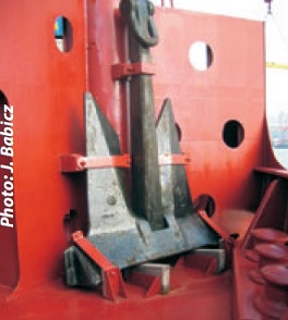
spare anchor AC 14
Fig: Spare anchor AC 14

Super high holding power anchor (SHHP) – To obtain the predicate SHHP, the anchor must have a holding power of at least four times the holding power of a conventional anchor.

Anchor chain, anchor cable – A heavy chain used for holding a vessel at anchor. The total length of chain is to be divided in approximately equal parts between the two bower anchors. The inboard ends of the chain cables are to be secured to the ship’s structure by means which enable, in case of emergency, an easy slipping of the chain cables to sea.

The windlass

The windlass is the usual anchor handling device where one machine may be used to handle both anchors. A more recent development, particularly on larger vessels, is the split windlass where one machine is used for each anchor.

One unit of a split windlass is shown in Figure . The rotating units consist of a cable lifter with shaped snugs to grip the anchor cable, a mooring drum for paying out or letting go of mooring wires and a warp end for warping duties. Each of these units may be separately engaged or disengaged by means of a dog clutch, although the warp end is often driven in association with the mooring drum.

A spur gear assembly transmits the motor drive to the shaft where the various dog clutches enable the power take-off. Separate band brakes are fitted to hold the cable lifter and the mooring drum when the power is switched off.

The cable lifter unit, shown in Figure below, is mounted so as to raise and lower the cable from the spurling pipe, which is at the top and centre of the chain or cable locker. Details of the snugs used to grip the cable and of the band brake can be seen.

Anchor capstans are used in some installations where the cable lifter rotates about a vertical axis. Only the cable lifter unit is located on deck, the driving machinery being on the deck below. A warping end or barrel may be driven by the same unit and is positioned near the cable lifter.

anchor Windlass
Figure : Deck anchor Windlass

Anchor windlass trials – Each windlass shall be tested under working conditions after installation on-board to demonstrate satisfactory operation. Each unit is to be independently tested for braking, clutch functioning, lowering and hoisting of chain cable and anchor, proper riding of the chain over the chain lifter, proper transit of the chain through the hawse pipe and the chain pipe, and effective proper stowage of the chain and the anchor. The mean hoisting speed is to be measured and verified, of each anchor and at least with 82.5m length of chain submerged and hanging free. The braking capacity is to be tested by intermittent paying out and holding the chain cable by means of the brake application.


Marine machineries - Useful tags

Marine diesel engines //Steam generating plant //Air conditioning system //Compressed air //Marine batteries //Cargo refrigeration //Centrifugal pump //Various coolers //Emergency power supply //Exhaust gas heat exchangers //Feed system //Feed extraction pump // Flow measurement // Four stroke engines // Fuel injector // Fuel oil system // Fuel oil treatment // Gearboxes // Governor // Marine incinerator // Lub oil filters // MAN B&W engine // Marine condensers // Oily water separator // Overspeed protection devices // Piston & piston rings // Crankshaft deflection // Marine pumps // Various refrigerants // Sewage treatment plant // Starting air system // Steam turbines // Steering gear // Sulzer engine // Turbine gearing // Turbochargers // Two stroke engines // UMS operations // Engine room safety // Drydocking & major repairs // Critical machinery //

Other info pages:

Marine diesel engines - Main propulsion machinery

Steam generating plant -Boiler arrangements

Feed systems for auxiliary boilers and steam turbines

Steam turbines - Energy conversion process

Fuel oil & lub oil treatment & centrifugal process

steering gear arrangement, testing & regulatory requirement

Pumps and pumping arrangement

Valves and pipelines for machinery spaces

Refrigeration of cargo spaces and storerooms

Heating, ventilation & air conditioning

Propeller shaft arrangement

Power generation , supply & distribution system

Deck machineries & cargo gears

Control and instrumentation

Fire protection

Engine room safety


Machinery Spaces.com is about working principles, construction and operation of all the machinery items in a ship intended primarily for engineers working on board and those who working ashore . For any remarks please Contact us

Copyright © 2010-2016 Machinery Spaces.com All rights reserved.
Terms and conditions of use
Read our privacy policy|| Home page||